
Treasury temperature measurement alarm circuit diagram F007 5G1555 F033

The temperature alarm circuit is designed to monitor temperature variations and activate an alarm when a specified threshold is exceeded. The inverting amplifier (IC1) serves to amplify the signal from the temperature sensor, which is crucial for detecting minute changes in temperature. The configuration of IC2 as a reference voltage comparator allows for precise comparison against a set voltage, enabling the circuit to trigger an alarm when the temperature surpasses the predetermined level.
The low-frequency multivibrator (IC3) plays a critical role by generating a stable frequency that can be adjusted to suit the application's requirements. This frequency can influence the response time of the system, ensuring that the alarm is activated promptly in case of temperature fluctuations. The controllable oscillation frequency multivibrator (IC4) allows for additional customization of the output signal, which can be tailored to the specific needs of the application.
The bridge measurement network, utilizing the germanium tube sensor (BY) and associated resistors, creates a sensitive and responsive measurement system. The use of potentiometers (W1, W2, W3, and W4) provides flexibility in calibration and adjustment, allowing users to fine-tune the system for various operating conditions. This ensures that the microammeter provides accurate readings and that the alarm triggers at the correct temperature.
In summary, this temperature alarm circuit is a sophisticated and adjustable system that effectively monitors temperature and activates an alarm when necessary. Its design incorporates various components and configurations that enhance its functionality, making it suitable for a wide range of applications where temperature monitoring is critical. As shown in FIG measuring temperature alarm circuit to the Treasury. The device consists of inverting amplifier IC1, comparison amplifier IC2, low-frequency multivibrator IC3, IC4 multivibrator controllable oscillation frequency, bridge measuring network, a speaker Y, the power supply circuit. Wherein the bridge is measured by a temperature sensor network BY (germanium tube 3AX31) a PN junction, resistors R1 ~ R4 and potentiometer W1 and other components.
IC1 (F033) with some RC components inverting amplifier, IC2 (F007) reference voltage comparator amplifier configuration connected to the inverting terminal of IC2. IC3 and RC components around 1Hz low frequency oscillator, which in turn controls the corresponding oscillation frequency of the multivibrator IC4.Circuit adjustable potentiometer W1 so that the bridge at 0 in equilibrium, so that the corresponding output of IC1 is about 0V, then microampere meter CB zeroing.
W2 potentiometer for adjusting the gain of the amplifier, so microampere meter scale reaches approximately 0.1V/. W3 potentiometer used to adjust the balance of the amplifier, so microampere meter CB indication zero.
W4 potentiometer for adjusting the amplifier IC2 reference comparison voltage, depending on the season and room temperature requirements to determine how high the temperature was powered alarm circuits, so that an alarm sound. Additional power contacts J1-1 alarm circuit is controlled by the relay IC2 output. When the high voltage of IC2 inverting terminal foot than inverting terminal feet when, IC2 output is a positive voltage, the D2 is turned on, the relay coil due to current flow and the J1-1 contact sticking.
Related Circuits
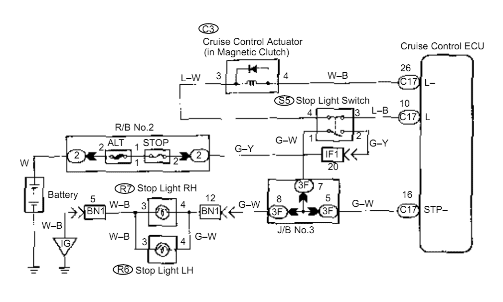
When the brake pedal is depressed, battery positive voltage normally applies through the STOP fuse and stop light switch to terminal STP of the ECU, and the ECU turns the cruise control off. A failsafe function is provided so...

The circuit consists of a PIC microcontroller, an in-circuit serial programming (ICSP) interface, an RS232 level translator, and an HD44780 LCD display. Initially, a scrolling message is shown using the show_intro function. When a serial input is detected, the...

The count switching circuit consists of an electronic switch and a pulse delay circuit for control. The count switching circuit is designed to manage the switching of signals in a controlled manner. The electronic switch serves as the primary component...

In this multivibrator circuit, frequency and pulse width can be separately controlled by using steering diodes (1N914) and two potentiometers. This multivibrator circuit utilizes steering diodes, specifically the 1N914 type, to enable independent control over both the frequency and pulse...

The following circuit illustrates a Selective Timer Alarm Circuit based on the 4060 Integrated Circuit (IC). Features include an automatic turn-off mechanism for the alarm after a specified duration. The Selective Timer Alarm Circuit utilizes the 4060 IC, which serves...
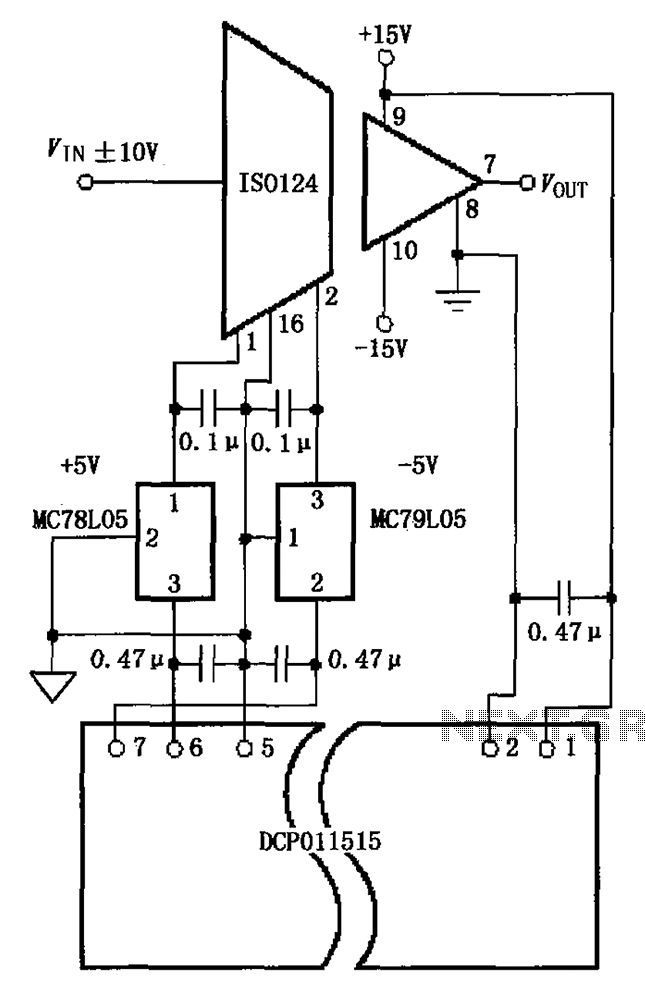
The circuit depicted in the figure includes the ISO124 and MC78L05 components, along with an external regulator, MC79L05, and the DCP011515, which collectively enhance the power supply rejection ratio (PSR) of the circuit. The input signal, VIN (maximum swing...