
Three water full alarm circuit
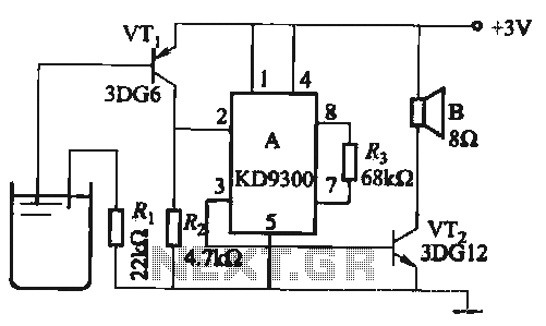
The circuit described is designed to generate an alarm tone through the manipulation of specific component values within the schematic. The components mentioned—Ri, R2, Cl, and C3—play crucial roles in determining the frequency and characteristics of the output sound.
Ri and R2 are resistors that, when adjusted, change the charging and discharging rates of the capacitors Cl and C3. These resistors form a part of an RC (resistor-capacitor) timing circuit, which is fundamental in generating audio frequencies. By varying the resistance values, the time constant of the circuit is altered, leading to different frequencies being produced.
Cl and C3 are capacitors that store and release electrical energy. Their capacitance values directly influence the timing characteristics of the circuit. A higher capacitance value results in a slower discharge rate, which can lower the frequency of the oscillation, while a lower capacitance value increases the frequency. The interaction between these capacitors and the resistors determines the waveform shape and tone of the sound generated.
The KD9300 music integrated circuit serves as the core of the alarm tone generator. This IC is designed to produce various musical tones and can be programmed or configured to generate specific sound outputs based on the input it receives from the RC timing circuit. The KD9300 typically contains internal oscillators and sound synthesis capabilities, allowing for versatile sound generation.
In summary, the alarm tone can be finely tuned by adjusting the resistor and capacitor values, which in turn modifies the RC time constants and affects the oscillation frequency produced by the KD9300. This allows for a range of tones suitable for alarm applications, enhancing the circuit's functionality and adaptability.Change the value Ri, R2, Cl, C3, can change the alarm tone. It uses KD9300 music integrated circuits.
Related Circuits
This circuit design has not been tested by staff. The design, as submitted by the designer, is believed to be correct; however, there is no guarantee of its accuracy. The content provided may be inaccurate, inappropriate, or misguided. There...
A minimum number of parts yields a compact switching converter that can provide sufficient voltage to drive white LEDs. The resulting lamp is much more efficient, in terms of lumen hours per pound of battery, than incandescent bulbs, and...
This schematic represents a version of a simple LED chaser. A 555 timer is not utilized due to its high cost at local electronics stores, which is over $4 CAD. Instead, an oscillator is constructed using two sections of...
The 555 circuit can be re-triggered if the input is held low for a duration longer than the output pulse. To prevent this from occurring, an additional timing circuit has been incorporated, consisting of a 1 Megohm resistor and...
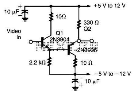
This circuit has demonstrated effectiveness as a video buffer and can easily drive a 75-ohm load to a 1.5-V peak-to-peak output. The bandwidth exceeds 20 MHz, and the DC offset is less than 0.05 V, attributed to the difference...

This circuit has the advantage of transferring almost all the energy from the collapsing magnetic field of L2 to C2. In contrast, a typical Joule thief circuit allows some of this energy to return to the battery. This efficiency...
Warning: include(partials/cookie-banner.php): Failed to open stream: Permission denied in /var/www/html/nextgr/view-circuit.php on line 713
Warning: include(): Failed opening 'partials/cookie-banner.php' for inclusion (include_path='.:/usr/share/php') in /var/www/html/nextgr/view-circuit.php on line 713