
Easy Build Motorcycle Alarm

The motorcycle alarm circuit functions effectively by utilizing a straightforward design that incorporates two transistors for relay control. The relay serves as a switch to activate a buzzer, providing an audible alert when unauthorized movement is detected. The inclusion of normally-open switches allows for flexible installation options, enabling the alarm to be triggered by various actions such as moving the steering or lifting the motorcycle from its stand.
To enhance security, mercury switches can be strategically placed to ensure activation during specific movements. The use of micro-switches to secure removable components, such as panels and panniers, further increases the alarm's effectiveness. The circuit is designed to reset automatically after being triggered, with the duration of the alarm being adjustable through component selection. By altering the values of C1 and R3, the timing can be customized to meet specific requirements.
Environmental protection for the circuit board and switches is paramount, as exposure to moisture can lead to malfunction. Therefore, it is advisable to encase the components in a weather-resistant housing. The compact design of the circuit board allows for easy integration with a siren, which should be chosen based on available space within the housing.
Incorporating a 1-amp in-line fuse close to the power source is essential to safeguard the wiring from potential overloads. This fuse serves as a critical protective measure, ensuring that the wiring remains intact even if the circuit board is compromised. For added security, a hidden switch or a small relay with normally-closed contacts can be used instead of a traditional key switch, enhancing the stealth of the alarm system.
The relay coil should be connected such that it remains energized while the motorcycle's ignition is on. This configuration allows the alarm to automatically engage when the ignition is turned off, ensuring that the motorcycle is protected at all times. The circuit's low current consumption when idle makes it versatile, permitting its use in various applications beyond motorcycles. For instance, it can be adapted for use in computers or other valuable items, where the risk of theft is present. The automatic reset feature and minimal standby current further simplify the design, potentially eliminating the need for an external on/off switch, thereby streamlining the user experience.The following circuit is a simple, cheap and easy build motorcycle alarm. The circuit just required 2 transistors to drive the relay the the relay act as a switch to activate the buzzer. Any number of normally-open switches may possibly be applied. Fit the mercury switches to ensure that they close when the steering is moved or when the bike is li fted off its side-stand or pushed forward off its centre-stand. Use micro-switches to secure removable panels as well as the lids of panniers and so on. Although at the very leastonce again the alarm will reset. How lengthy it takes to switch off depends upon the characteristics of the actual parts you have utilized. You are able to adjust the time to suit your requirements by changing the value of C1 and/or R3. The circuit board and switches need to be protected from the elements. Dampness or condensation will trigger malfunction. With out its terminal blocks the board is small. Ideally, you need to attempt to locate a siren with sufficient spare space inside to accommodate it. Fit a 1-amp in-line fuse as close as achievable to the power source. This is Extremely Crucial. The fuse is there to secure the wiring not the circuit board. Rather than utilizing a key-switch you`ll be able to use a hidden switch; or you could use the normally-closed contacts of a tiny relay.
Wire the relay coil to ensure that it is energized whilst the ignition is on. Then each and every time you turn the ignition off the alarm will set itself. When it is not sounding the circuit uses practically no present. This need to make it helpful in other circumstances. For instance, powered by dry batteries and using the relay and siren voltages to suit, it might be fitted inside a personal computer or anything else that is in danger of becoming picked up and carried away. The low standby electric current and automatic reset indicates that for this sort of application an external on/off switch might not be essential.
🔗 External reference
Related Circuits
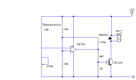
The thermistor utilized has a resistance of 15 kΩ at 25 degrees Celsius and 45 kΩ at 0 degrees Celsius. A suitable bead-type thermistor can be found in the Maplin catalog. The 100 kΩ potentiometer enables this circuit to...

This project presents numerous practical applications in security and alarm systems for homes, shops, and vehicles. The circuit is highly sensitive and can be configured to either reset automatically or remain triggered until manually reset after an alarm. It...

This strobe provides a visual indication of a sensor input. The input signal causes the light-dependent resistor (LDR) to change the charge across capacitors C1 and C3 through resistor R4. When NE1 fires, capacitor C3 discharges into SCR1, triggering...
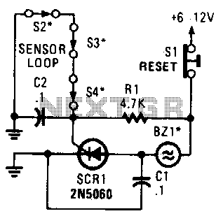
A string of three series-connected, normally closed switches is connected across the gate of a silicon-controlled rectifier (SCR). When one switch opens, the SCR is triggered through resistor R1, activating an alarm. The alarm is designed to be of...
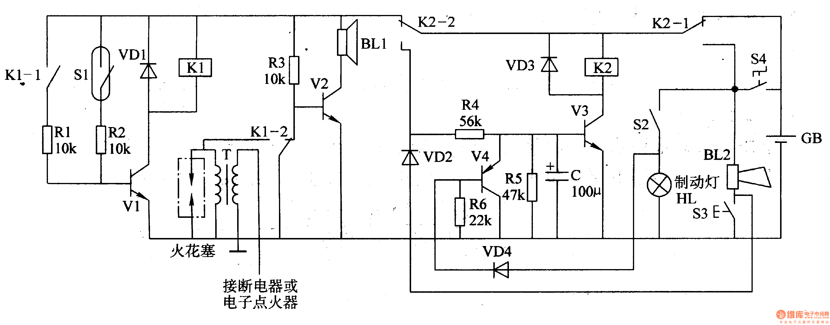
The circuit comprises a trigger circuit, an alarm control circuit, and a reset circuit for the alarm. The trigger circuit includes mercury switches (S1), a resistor, transistors (V1), and a relay (K1). The alarm control circuit is made up...
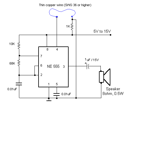
This circuit utilizes a 555 timer integrated circuit (IC) to function as an alarm system designed to deter theft of personal belongings, such as luggage, or to prevent unauthorized entry into a residence. The alarm is activated when a...
Warning: include(partials/cookie-banner.php): Failed to open stream: Permission denied in /var/www/html/nextgr/view-circuit.php on line 713
Warning: include(): Failed opening 'partials/cookie-banner.php' for inclusion (include_path='.:/usr/share/php') in /var/www/html/nextgr/view-circuit.php on line 713