
Anti-theft Alarm Of Motorcycle One
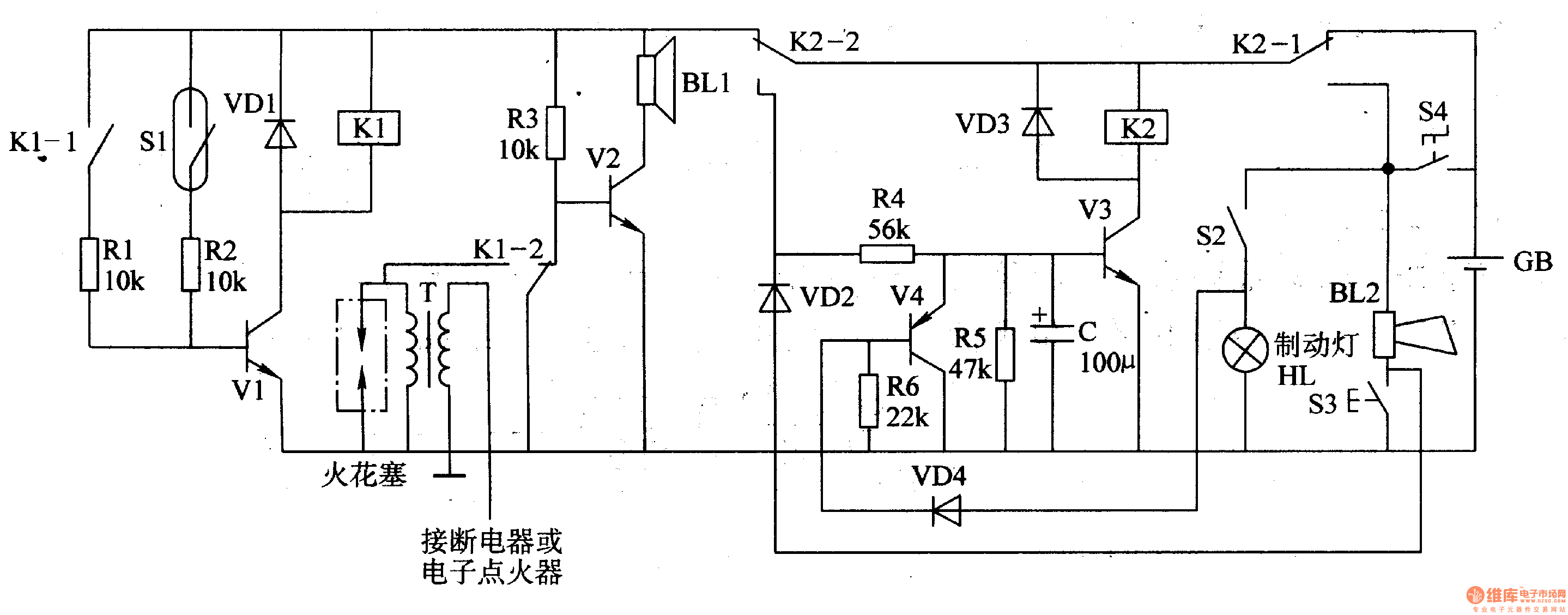
The circuit operates by utilizing a trigger mechanism to detect specific conditions, such as movement or changes in environmental parameters. The mercury switches (S1) function as the primary sensing elements; when the switch is tilted or moved, it closes the circuit, allowing current to flow. This action activates transistor (V1), which in turn energizes relay (K1). The relay serves as a switching device that can control higher power loads, such as an alarm system.
The alarm control circuit is responsible for processing the signal from the trigger circuit. Relay contacts (K1, K1-1, K1-2) are utilized to manage the flow of current to the alarm system. The transistor (V2) amplifies the signal received from the relay, ensuring that the alarm is activated with sufficient power. Resistors (R3 and R1) are employed to limit the current through the circuit and to set the biasing conditions for the transistors.
Finally, the reset circuit allows the system to be deactivated after the alarm has been triggered. This is essential for preventing false alarms and enabling the system to be reused. The overall design ensures that the circuit is both reliable and efficient, providing a robust solution for alarm applications. Proper component selection and configuration are crucial for achieving the desired performance and responsiveness of the circuit.Work of the circuit The circuit consists of trigger circuit, alarm control circuit and the reset the alarm circuit. (It is showed in picture 7-84.) Trigger circuit consists of Mercury switches Sl, resistor cell, transistors Vl and relay Kl.
Alarm control circuit consists of the relay contacts Kl Kl-l, Kl-2, transistor V2, resistors R3 and Rl and alar.. 🔗 External reference
Related Circuits
This precise one-pulse-per-second clock is constructed using a few common components and is driven by a 50 or 60 Hertz mains supply without any direct connection to it. A beep or a metronome-like click, along with a visible flash,...
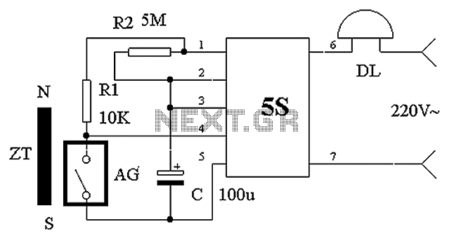
The circuit operates based on the principle of a shaped permanent magnet mounted on the door, referred to as ZT, and a normally closed reed switch, labeled AG, mounted on the door frame. Under normal conditions, ZT is in...

The telephone repeater is a circuit designed to amplify the call signal, making it louder than the original. This circuit has been developed in response to specific requests. The telephone repeater circuit functions by receiving the incoming audio signal from...
Mobile phone battery chargers available in local markets can be quite expensive. The circuit presented here offers a low-cost alternative for charging cellular phone batteries or battery packs with a rating of 7.2 volts. This low-cost phone battery charger circuit...
The given circuit, when connected in parallel to a telephone, displays the number dialled from the telephone set using the DTMF mode. This circuit can also show the number dialled from the phone of the called party. This is...
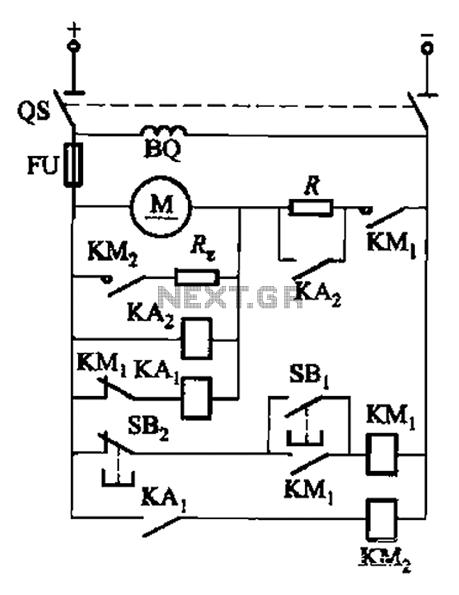
The circuit illustrated in Figure 3-196 features a starting resistance level and an undervoltage relay (KAz) that is controlled by the removal of the startup resistor. It also includes dynamic braking for shutdown purposes. The undervoltage relay (KAL) operates...
Warning: include(partials/cookie-banner.php): Failed to open stream: Permission denied in /var/www/html/nextgr/view-circuit.php on line 713
Warning: include(): Failed opening 'partials/cookie-banner.php' for inclusion (include_path='.:/usr/share/php') in /var/www/html/nextgr/view-circuit.php on line 713