
theft preventer alarm circuit
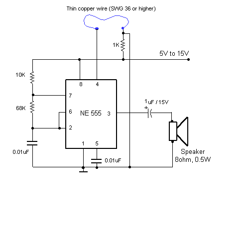
The alarm system employs a 555 timer IC, which is a versatile component often used in timer, delay, pulse generation, and oscillator applications. In this configuration, the 555 timer is set up as an astable multivibrator, meaning it continuously oscillates between its high and low states without any external triggering. This oscillation creates a square wave output that can be used to drive a speaker or piezo buzzer, generating an audible alarm sound.
The circuit consists of the following key components:
1. **555 Timer IC**: The core component that generates the oscillating signal. It has three main pins of interest: the discharge pin (Pin 7), the threshold pin (Pin 6), and the trigger pin (Pin 2). Resistors and capacitors connected to these pins determine the frequency of the output signal.
2. **Resistors (R1 and R2)**: These resistors set the timing intervals for the 555 timer. The ratio of these resistors, along with the capacitor, determines the frequency of the output tone. For a frequency of approximately 1 kHz, suitable resistor values might be in the range of 1 kΩ to 10 kΩ.
3. **Capacitor (C1)**: This capacitor works in conjunction with the resistors to establish the timing cycle of the 555 timer. A typical value for this capacitor could be around 10 µF, but it can be adjusted to modify the frequency of the output sound.
4. **Thin Wire Sensor**: The thin wire acts as a switch that closes the circuit when intact and opens when disturbed. This wire can be strategically placed around luggage or entry points to detect unauthorized access. When the wire is cut or broken, it triggers the 555 timer to start oscillating, thus activating the alarm.
5. **Speaker or Buzzer**: This component converts the electrical signal from the 555 timer into sound. A piezoelectric buzzer is often used for its simplicity and effectiveness in producing loud sounds.
The circuit can be powered by a standard 9V battery, allowing for portability and ease of installation in various locations. The design is compact and can be housed in a small enclosure, making it suitable for discreet placement in luggage or home security applications.
Overall, this alarm system effectively combines simplicity with functionality, providing an accessible solution for enhancing security against theft and unauthorized entry.This circuit utilising a 555 timer IC can be used as an alarm system to prevent the theft of your luggage, burglars breaking into your house etc. The alarms goes ON when a thin wire, usually as thin as a hair is broken. The circuit is straightforward. It uses a 555 IC wired as an astable multivibrator to produce a tone of frequency of about 1kHz w hich gives out a shrill noise to scare away the burglar. 🔗 External reference
Related Circuits
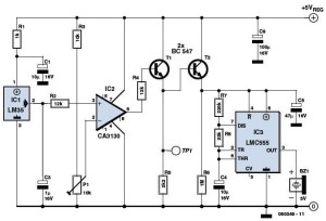
The overhead detector (fire alarm) circuit utilizes a precision integrated temperature sensor, the LM35 (IC1), which offers an accurate linear output. The overhead detector circuit is designed to monitor ambient temperature levels for fire detection purposes. The core component of...
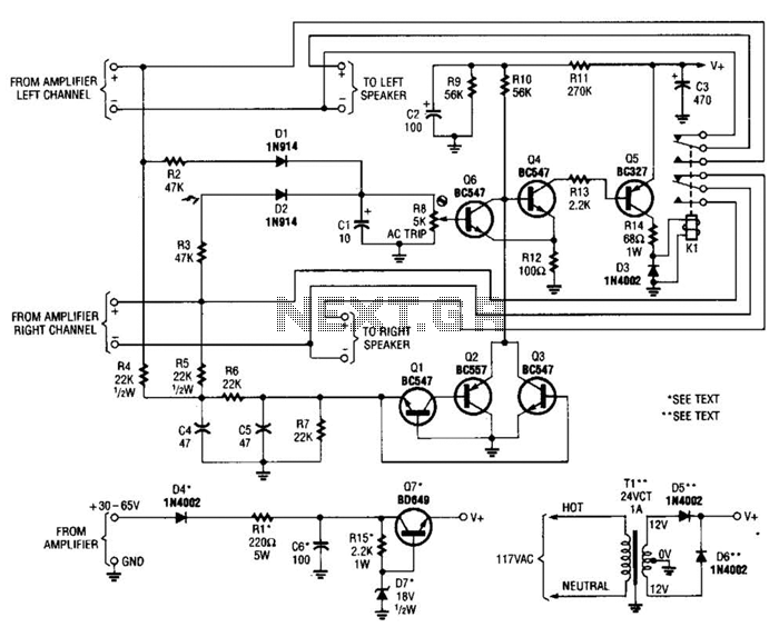
Most of the transistors in this speaker protector operate as switches. Normally, Q4, Q5, and K1 are activated, allowing the speakers to connect to the amplifier. However, if a significant DC voltage is detected at the amplifier output, either...
This amplifier is designed to be self-contained within a compact loudspeaker enclosure. It can be powered by devices such as Walkmans, Mini Discs, iPods, CD players, computers, and other devices equipped with line or headphone outputs. Typically, two units...
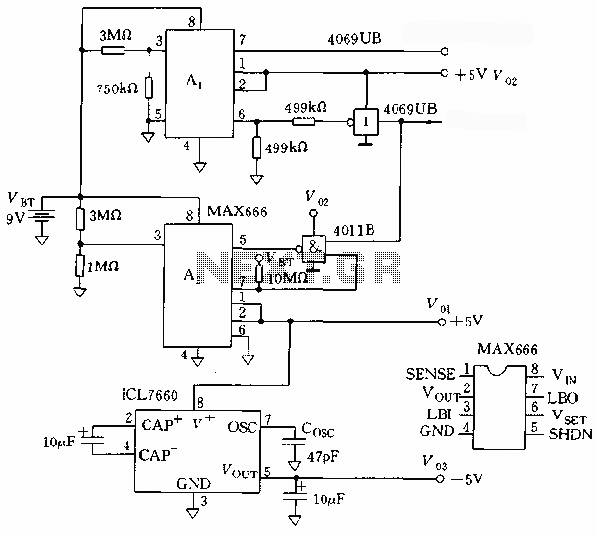
The microprocessor utilizes a linear regulator power circuit that is constructed using two MAX666 devices. The power supply for the CPU and A/D converter is connected to A2, while the RAM and real-time clock receive power from A1. The...
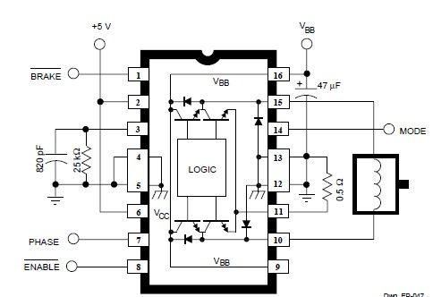
This simple DC servo motor circuit design can be utilized in various electronic projects. The circuit schematic illustrates that this DC servo motor driver employs a single integrated circuit along with a few external electronic components. For bidirectional DC...
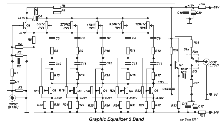
Another unit of graphic equalizer with five bands. The primary distinction from other circuits is the use of transistors instead of integrated circuits (ICs), and the power supply operates at +/- 24V DC, which ensures low distortion and greater...
Warning: include(partials/cookie-banner.php): Failed to open stream: Permission denied in /var/www/html/nextgr/view-circuit.php on line 713
Warning: include(): Failed opening 'partials/cookie-banner.php' for inclusion (include_path='.:/usr/share/php') in /var/www/html/nextgr/view-circuit.php on line 713