
Easy exchange of magnetic saturation voltage regulator circuit
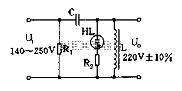
The magnetic saturation voltage regulator circuit is designed to stabilize output voltage levels by utilizing magnetic saturation principles. This circuit typically employs a magnetic core, which operates in saturation to regulate voltage, ensuring minimal fluctuations in output despite variations in load or input voltage. The primary components of this circuit include a transformer, diodes, and a feedback mechanism that monitors the output voltage.
The transformer is crucial in stepping down the input voltage to a manageable level before it is rectified by the diodes. The diodes convert the AC voltage from the transformer into DC voltage, which is then smoothed using capacitors to reduce ripple. The feedback mechanism is essential for maintaining voltage stability; it continuously compares the output voltage to a reference voltage and adjusts the control signal accordingly.
When the output voltage rises above the desired level, the feedback loop reduces the current flowing through the transformer, effectively bringing the output voltage back into the acceptable range. Conversely, if the output voltage drops, the feedback loop increases the current to compensate. This dynamic adjustment allows the magnetic saturation voltage regulator to maintain a constant output voltage even under varying load conditions.
The design of this circuit can be optimized for efficiency by selecting appropriate components and tuning the feedback loop for quick response times. Additionally, considerations for thermal management should be made, as components may generate heat during operation. Overall, the magnetic saturation voltage regulator circuit presents a reliable solution for applications requiring stable voltage regulation.Easy exchange of magnetic saturation voltage regulator circuit
Related Circuits
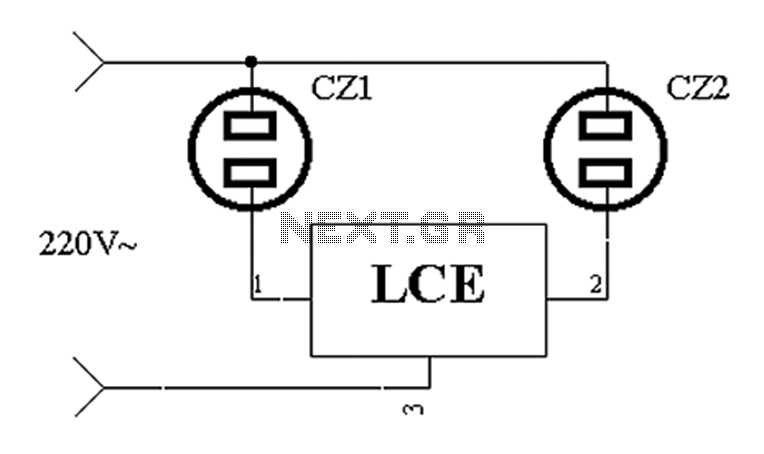
The application circuit operates the device as illustrated below. It is designed for cooling electrical equipment, typically utilizing a cooling fan to dissipate heat. The LCE employs a synchronous control socket on the device and its connections remain unchanged....
More: The input data lacks specific content, providing only placeholders without any detailed information. In the context of electronic schematics, a comprehensive description typically involves detailing the components, their interconnections, and the overall functionality of the circuit....
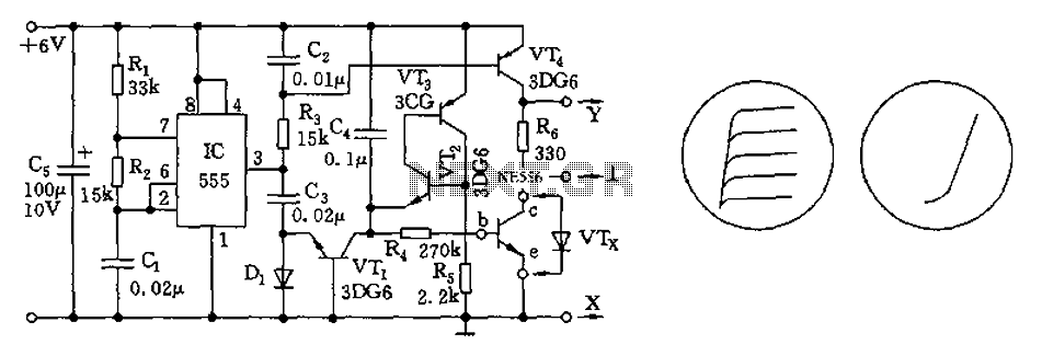
The transistor characteristic curve tracer circuit depicted in Figure 555 illustrates the characteristics of a transistor. It utilizes two voltages: a step wave applied to the base (b) to generate different base currents (Ib), and a sawtooth waveform at...
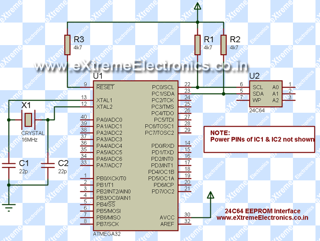
An EEPROM is a type of non-volatile memory, which means it is used for permanently storing digital data without any power supply. EEPROM stands for Electrically Erasable Programmable Read-Only Memory. The advantage of this type of ROM is that...
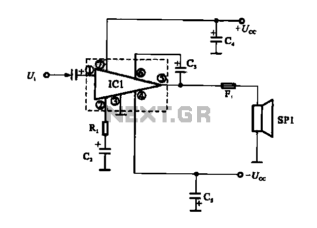
The OCL power amplifier circuit is an integrated circuit. Circuit IC1 is an integrated circuit, and its internal circuit configuration is substantially similar to the OTL power amplifier circuits. The OCL (Output Capacitor-Less) power amplifier circuit is designed to provide...
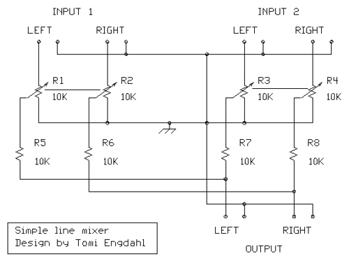
The mixer circuit described features three line inputs and three microphone inputs. The microphone inputs are designed for low impedance dynamic microphones with a range of 200 to 1000 ohms. Alternatively, an electret condenser microphone (ECM) can be used,...