
IC OCL power amplifier circuit
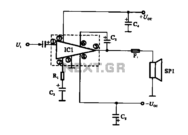
The OCL (Output Capacitor-Less) power amplifier circuit is designed to provide high-quality audio amplification while eliminating the need for output coupling capacitors. This feature enhances the overall efficiency of the circuit, allowing for a more compact design with fewer components. The integrated circuit IC1 serves as the core of the amplifier, which typically includes multiple transistors configured to handle both the voltage and current requirements of the output stage.
The internal configuration of IC1 closely resembles that of OTL (Output Transformer-Less) power amplifier circuits, which also prioritize efficiency and sound quality. In OCL designs, the output stage is directly connected to the load (such as speakers) without the use of transformers, allowing for a wider frequency response and reduced distortion.
In the OCL configuration, the circuit may employ feedback mechanisms to stabilize gain and improve linearity. The biasing of the transistors is crucial, as it determines the operating point and can significantly impact the performance characteristics of the amplifier, such as thermal stability and distortion levels.
The power supply requirements for an OCL amplifier typically involve a dual power supply, providing both positive and negative voltages to accommodate the AC signal swing. Careful attention must be paid to the power supply decoupling to minimize noise and ensure stable operation.
Overall, the OCL power amplifier circuit is a sophisticated solution for audio amplification, combining the benefits of integrated circuit technology with the high performance of advanced amplifier design principles.FIG OCL power amplifier circuit is an integrated circuit. Circuit IC1 is an integrated circuit, its internal circuit configuration is substantially similar to the integrated ci rcuit OTL power amplifier circuits.
Related Circuits
This indicator lets you see how much power an amplifier produces. The circuit uses an LM 3915, the logarithmic variation of the known IC LED VU Meter LM 3914. The circuit is connected directly to the speaker output of...
The gain of the low-cost integrated circuit (IC) is internally fixed at no less than 34 dB (50 times). A unique input stage allows input signals to be referenced to ground. The output is automatically self-centering to one-half the...
The 555 timer on the right is configured as an alarm sound generator, while the second 555 timer on the left operates as a 1 Hz astable multivibrator. The output from the left timer modulates the frequency of the...
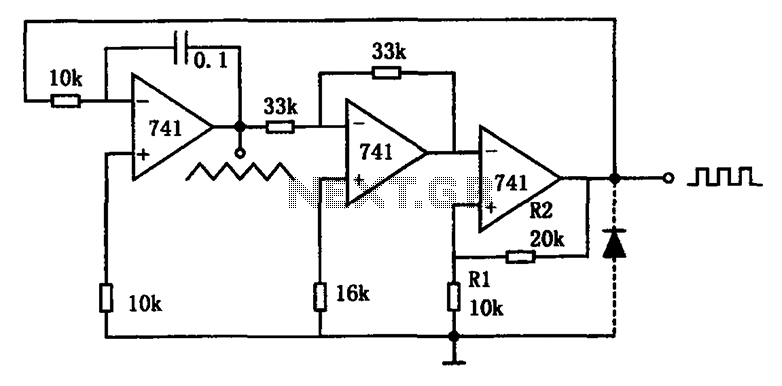
The circuit illustrated generates a variety of low-frequency waveforms, specifically triangle and square waves, simultaneously. It consists of several stages: the first stage is an integrator, followed by a gain stage with an inverter, and a comparator stage that...
A circuit is required where, upon power application, a timer triggers, keeping a relay in the off state. Once the timer completes its cycle, the relay will activate. The circuit design consists of a timer integrated with a relay to...
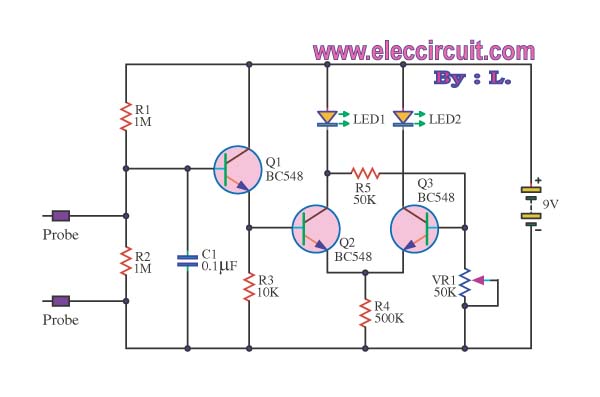
This is a false capture circuit or lie detector circuit. The basic principle is based on the resistance of human skin. While dry skin has a resistance of about 1 Megaohm. The lie detector circuit utilizes the principle of galvanic...