
Easy fades fade switching circuit 2
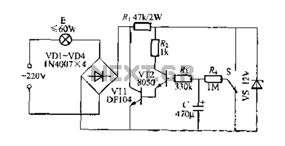
This circuit utilizes a straightforward design to achieve a dimming effect for lighting applications. The core components include a capacitor (C), resistors (R and R1), and transistors (VT1 and VT2). The circuit operates by leveraging the charging and discharging characteristics of the capacitor to control the brightness of the lamp (E).
When the circuit is powered, the capacitor begins to charge through resistor R, resulting in a gradual increase in voltage across the capacitor. This increase influences the base of transistor VT2, allowing it to turn on progressively. As VT2 conducts, it reduces the effective resistance presented by high-power transistor VT1, which is responsible for driving the lamp. The lamp (E) thus brightens smoothly as the voltage rises, providing a visually appealing fade-in effect.
Conversely, when the switch is turned to the off position, the capacitor begins discharging through resistor R. This discharge process allows the lamp to remain lit for a brief period, but the brightness diminishes gradually as the capacitor voltage drops. The time it takes for the lamp to extinguish completely depends on the values of the capacitor and resistor used in the circuit, which can be adjusted to achieve the desired fade-out duration.
The circuit's design is robust, with no specific requirements for the transistors or other components, allowing for flexibility in component selection. The high back pressure rating for resistor R1 is crucial to ensure reliable operation under varying load conditions. Overall, this gradual clear/fade switch circuit is an effective solution for applications requiring controlled lighting transitions.End a two-wire connection gradually clear/fade switch circuit when the circuit is relatively simple to install. Turn on the lights when needed, H properly switch S dial upward, positive supply via] 2V R. The capacitor (1 charge, the C voltage across gradually increased, so make VT2 gradually step guide Annals of people, high-power tube VT1 equivalent resistance decreased, lamp E gradually brighten the dark. When the C full charge the brightness of the lamp will no longer change when you turn off the lights of the store s dial downward, C.
charge Pan R; to VT2 discharge lamp can be maintained light, but dichotoma brightness gradually darken over time, when (- charge when basic is done and the lights went completely extinguished. v r1 should be high back pressure power NI, N transistors, other components, no special requirements.
Related Circuits
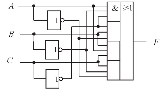
The design of the combinational logic circuit is diverse. An example chosen for detailed explanation is the implementation of an even parity check circuit. The parity check circuit exhibits particular characteristics and practicality in the analysis and design of...

This simple mock flasher LED simulates the indicator of a sophisticated alarm system. It can be placed in doors, gates, and vehicles to confuse intruders. The mock flasher LED circuit is designed to mimic the flashing behavior of a typical...
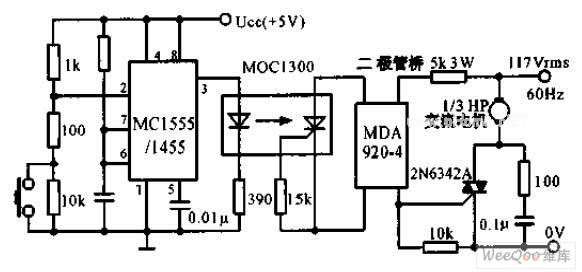
The switch shut-off time delay circuit consists of a timer, optocouplers, a bridge SCR, and an SCR AC switch. When the control button is released, it allows the motor or other AC power to remain active for one hour....
The AM transmitter circuit consists of an audio amplifier and an RF oscillator. The oscillator is constructed around transistor Q1 and its associated components. The tank circuit, which includes inductor L1 and variable capacitor VC1, is tunable from approximately...

This is a design of the circuit diagram for an RS422 interface. Connector K1 is connected to the serial port of the PC, and power for the PC side of the circuit is obtained from the signal lines DTR...

This document outlines the design process of a control circuit for a stepper motor. Given the characteristics of the stepper motor, the control circuit was developed as a state machine that transitions through four output states depending on two...