
ECG telemetry circuit diagram
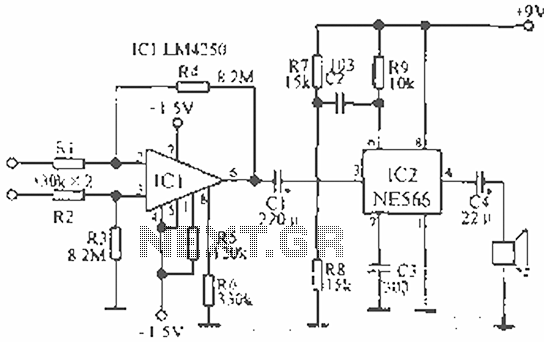
The described circuit serves as an educational tool for demonstrating the principles of electrocardiography and audio signal processing. The core component, the LM4250 operational amplifier, is utilized to amplify the weak ECG signal captured from the patient. The amplified signal is then fed into the NE566 voltage-controlled oscillator, which converts the varying voltage levels of the ECG signal into corresponding frequency changes. This modulation allows for the direct auditory representation of the electrical activity of the heart.
The output from the NE566 is connected to a small speaker, which translates the modulated signal into sound waves. This enables observers to hear the heartbeats and variations in heart rhythm in real-time, facilitating a better understanding of cardiac function. For telemetry applications, the circuit can be enhanced by incorporating a microphone that captures the sound output, allowing for remote monitoring of the ECG signal.
To connect the circuit to a patient, standard viscous monitor electrodes are recommended for optimal contact and signal quality. Alternatively, small metal pieces can be affixed to the patient’s wrist using a rubber band, ensuring that the electrical signals are reliably transmitted to the circuit. This setup allows for a practical demonstration of how electrical signals from the heart can be monitored and analyzed, making it an invaluable tool for educational purposes in electronics and biomedical engineering. The pitch of the sound produced varies with each heartbeat, providing an auditory cue that corresponds to the heart's electrical activity, thus illustrating the relationship between physiological signals and electronic processing.The circuit designed for teaching demonstration or experiment with it to hear the signal voltage electrocardiogram. ECG signal voltage is amplified by the LM4250 operational amplifier connected to a voltage-controlled oscillator NE566 to modulate the oscillator output is used to drive a small speaker, so you can hear the ECG signal. If you want to telemetry, you can use the microphone to pick up the sound output. To put this circuit and the patient connected, you can use the standard viscosity monitor electrodes can also be used a rubber band to tie small metal pieces on the patient's wrist.
Each pulse will cause the pitch frequency changes.
Related Circuits
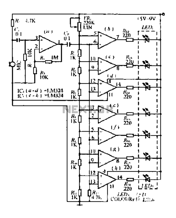
The condenser microphone pickup signal is processed by an integrated circuit (IC) where it is amplified and compared using a comparator circuit. The outputs from the comparators, designated as IC1, IC2, and IC3, provide voltage comparisons based on different...
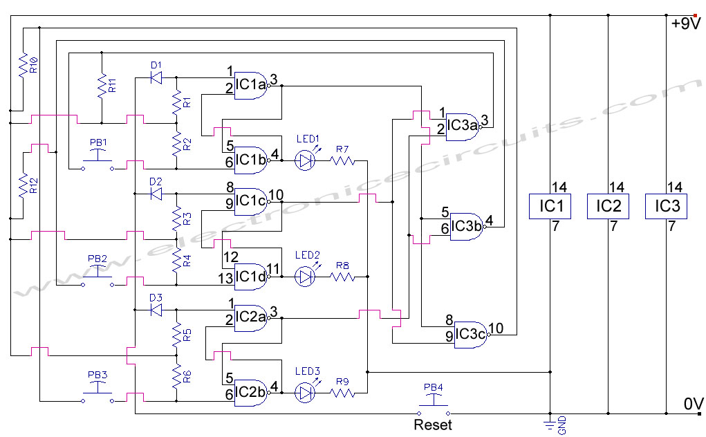
First Response Monitor, Input Selector, Game Circuit. This circuit is utilized for first response applications as it aids in monitoring various responses in games. The First Response Monitor circuit is designed to facilitate real-time monitoring and selection of input signals...
Figure A illustrates the schematic of a microstrip single-stage RF amplifier. This amplifier utilizes the M/A-Com LF2810A MOSFET, which is rated for 10 watts and operates at 28 volts, but it delivers sufficient gain for this application at a...
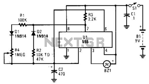
This timer circuit utilizes a 555 IC timer in conjunction with three 74LS193 counters to control an LED display. The circuit is activated by one individual who turns on the piezo buzzer BZ1 through Q1, simultaneously starting the timer....
This audio noise filter circuit is a bandpass filter designed for the audio frequency range. It effectively filters out unwanted signals that fall outside the audio frequencies. The circuit consists of two filters: a low-pass filter and a high-pass...
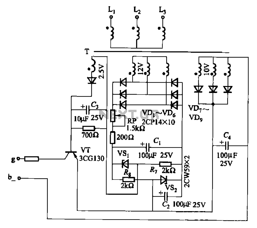
The CJ-12 Excitation Regulator is designed for automatic excitation control of small generators with a capacity of 250 kW or less. Its circuit is illustrated in Figure 7-45. The adjustment potentiometer RP allows for the modification of the measuring...