
2W RF Amplifier with MOSFET LF2810A circuit diagram
The microstrip single-stage RF amplifier is designed to operate in radio frequency applications, where efficiency and gain are critical. The choice of the M/A-Com LF2810A MOSFET is significant due to its ability to handle high power levels while maintaining linearity and low distortion. Operating at a supply voltage of 12 VDC allows for a balance between power efficiency and performance, making it suitable for various RF applications.
Input and output matching is essential in RF circuits to maximize power transfer and minimize reflections. The use of trimmer capacitors allows for fine-tuning of the matching network, accommodating variations in component values and ensuring optimal performance across the desired frequency range. The trimpot for adjusting the gate bias voltage plays a crucial role in controlling the amplifier's output power, providing flexibility for different operational requirements.
The circuit board layout, as depicted in Figure B, is critical for the performance of the amplifier. The choice of 0.030-inch Duroid material is ideal for RF applications due to its low dielectric loss and stable electrical properties over a wide frequency range. The compression soldering of the circuit board onto the copper heat spreader enhances thermal management, ensuring that the MOSFET operates within safe temperature limits, thereby prolonging its lifespan and maintaining reliability.
The precision milling and drilling of both the circuit board and the heat spreader are vital for accurate alignment and secure mounting of the flange-mount transistor. This attention to detail in the mechanical design contributes to the overall performance and stability of the RF amplifier, making it a robust solution for high-frequency applications.Figure A is the schematic of the microstrip single stage RF amplifier. The amplifier is based on the M/A-Com LF2810A MOSFET. The transistor is actually a 10 watt, 28 volt part, but provides adequate gain for this application at 12 VDC. The amplifier provides greater than 40% efficiency at the desired output power. Trimmer capacitors are used for i nput and output matching. Output power is adjusted by a trimpot which sets the gate bias voltage. Figure B is the layout for the microstrip circuit board. The board material is 0. 030 inch Duroid. The circuit board is compression soldered onto a similarly sized copper heat spreader. The board and spreader are milled and drilled to accept the flange-mount transistor. 🔗 External reference
Related Circuits
The Reaction Capability Tester is utilized to assess and enhance an individual's quick-response abilities. It features various designs, with the depicted model comprising a CD4017 decimal counter and a light-emitting diode (LED). The construction of the Reaction Capability Tester...
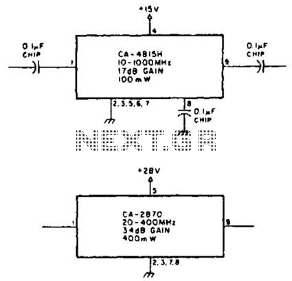
Using TRW part number CA-815H, a 17 dB gain amplifier capable of delivering 100 mW over a frequency range of 10 to 1000 MHz can be constructed. Additionally, the CA-2870 can provide 0.4 W with a gain of 34...
Figure a illustrates a multivibrator circuit capable of generating a square wave signal. Figure b depicts a flip-flop circuit that utilizes the falling edge of the input signal to produce a trigger pulse signal. Figure c represents a monostable...

This circuit is used to select modes of operation. The accelerometer is utilized to generally move the snake arm, while the Hall effect sensors are designed to enable various functions. The circuit described incorporates an accelerometer and Hall effect sensors...
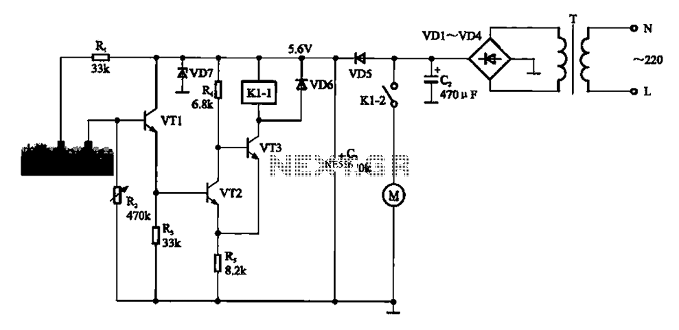
Automatic sprinkler control circuit. This circuit primarily consists of a humidity sensor, a detection signal amplifying circuit (including transistors VT1, VT2, and VT3), a power supply circuit (comprising a filter capacitor C2, a bridge conditioning circuit UR, and a...
This schematic illustrates a highly sensitive microphone preamplifier circuit designed to amplify the gain of a microphone or enhance audio signals originating from a microphone. The circuit is straightforward, comprising only a few components, and can be assembled in...