
Cellphone Operated Robot using ATmega16 AVR microcontroller

The National Robotics Week Robot Contest encourages innovation and creativity in robotics among participants aged 13 to 18. This category represents a significant opportunity for young engineers and robotics enthusiasts to showcase their skills in designing and building robotic systems. Participants are expected to create a project that demonstrates their understanding of robotics principles, including mechanics, electronics, and programming.
In this context, a typical project may involve the design of a mobile robot equipped with sensors for obstacle detection, a microcontroller for processing inputs, and motors for movement. The schematic for such a robot would include the following components:
1. **Microcontroller**: The central processing unit of the robot, which could be an Arduino or Raspberry Pi, responsible for executing the control algorithms and processing sensor data.
2. **Power Supply**: A battery pack providing the necessary voltage and current to power the microcontroller, motors, and sensors. The voltage requirements will depend on the specifications of the components used.
3. **Motors**: DC motors or stepper motors for driving the robot. The schematic will illustrate how these motors are connected to the microcontroller through a motor driver circuit, which allows for control of the motor speed and direction.
4. **Sensors**: Ultrasonic sensors for distance measurement, infrared sensors for line following, or cameras for vision processing. Each sensor will have specific connections to the microcontroller's input pins.
5. **Communication Modules**: If the robot is designed for remote operation or telemetry, modules such as Bluetooth or Wi-Fi may be included in the schematic, allowing for wireless communication.
6. **Chassis and Mechanical Components**: The physical structure of the robot, including wheels, frames, and mounts for the components, would be designed to ensure stability and mobility.
The final schematic would clearly label each component, indicate the connections between them, and provide values for resistors, capacitors, and other passive components used in the circuit. This comprehensive approach not only aids in the construction of the robot but also serves as an educational tool, illustrating the integration of various engineering disciplines in robotics.This Instructible is entered in the Category: 13 - 18 of the National Robotics Week Robot Contest. 🔗 External reference
Related Circuits
Connect any I2C client chip (such as temperature sensors, analog-to-digital converters, displays, or relay drivers) to your PC via USB quickly, easily, and affordably. Drivers are available for both Linux and Windows operating systems. The described system facilitates the integration...
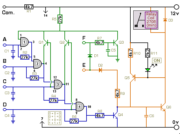
The key connected to "E" is used to energize the relay, while the four keys connected to A, B, C, and D are used to de-energize it. All other keys on the keypad are connected to "F". When "E"...
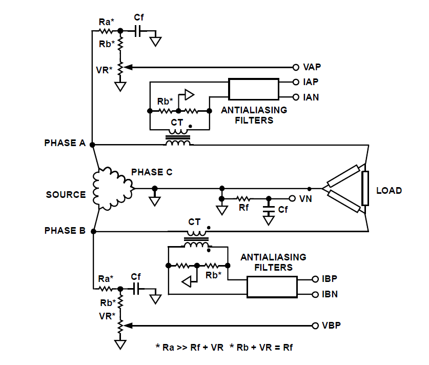
How can a circuit be built for digital readout of three-phase power consumption in a home using a chip like ADE7762? There is an interest in polyphase energy metering. To construct a circuit for digital readout of three-phase power consumption...
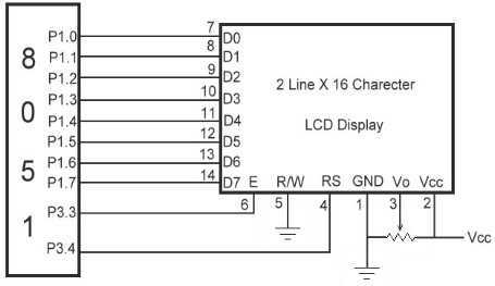
The link shows how to interface Alphanumeric LCD to 8051 Microcontroller. Liquid Crystal Display also called as LCD is very helpful in providing user interface as well as for debugging purpose. The most common type of LCD controller is...
This project provides a simple temperature-controlled fan. If the difference between the actual temperature and the user-defined temperature is significant, the fan will operate. The temperature-controlled fan circuit utilizes a temperature sensor, a microcontroller, and a fan motor to regulate...
Built around a single 8038 waveform generator IC, this circuit produces sine, square or triangle waves from 20Hz to 200kHz in four switched ranges. There are both high and low level outputs which may be adjusted with the level...