
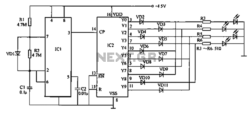
Voice-activated light switch delay circuit 1

The described light control delay switch circuit employs a clap-activated mechanism to control the illumination of a lamp. The design incorporates a microphone or sound sensor that detects the sound of clapping. Upon receiving a specific number of claps within a designated timeframe, the circuit triggers a transistor that completes the circuit for the lamp, allowing it to light up.
The transistor (VT) serves as the primary switching element, while the base resistance (R) is crucial for controlling the transistor's activation threshold. The integrated circuit (IC) plays a vital role in processing the input signal from the sound sensor, ensuring that only the intended clap signals are recognized and processed. The modifications to the circuit include the adjustment of the resistor values and the integration of a capacitive delay element (C) that collectively determine the timing characteristics of the lamp's illumination.
The adjustable delay feature is achieved by allowing the user to change the values of resistors (R) and capacitors (C) in the circuit. By altering these components, the delay time for the lamp can be extended or shortened, providing flexibility based on user requirements. This adaptability ensures that the lamp remains lit for a user-defined duration after activation, enhancing user experience and functionality.
In summary, this light control delay switch circuit is designed for effective clap detection and lamp control, with robust anti-interference capabilities and customizable delay settings. The circuit's efficiency and versatility make it suitable for various applications where hands-free operation and adjustable timing are desired.A strong anti-interference ability Lu light control delay switch circuit, it needs within a specific time in a row clapping I. lamp lit square Xi, after a delay, lights automat ically turn off. Ji Guan on this circuit example is basically the same, except that the transistor VT base resistance R. Original left foot then Sk t integrated circuits ? ? change received the first leg, and then affixed in ?tJ. ? feet respectively resistive and capacitive delay element R. And G, put the original voice of the city open to change Yan Ge opening delay. Changes in R;, c. Numerical length adjustable circuit of a specific time; change R, value then adjust the delay time of the circuit-cho, namely E lamp lighting the length of time the reader according to their own needs to be adjusted.
Related Circuits
Prolonged reading or writing, maintaining a close distance between the eyes and the book, and insufficient lighting are primary contributors to decreased vision. This example describes a visual fatigue eliminator designed to alleviate eye fatigue and prevent myopia. The...
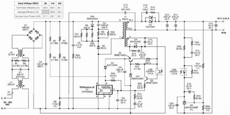
The TOP269EG off-line switcher integrated circuit (IC), designated as U1, can be utilized in a flyback configuration to create a simple and highly efficient power adapter for notebook laptops. The TOP269EG features an integrated 725 V MOSFET and a...
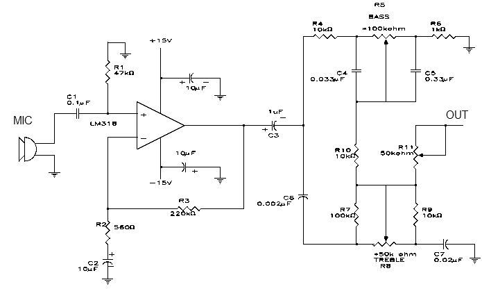
This simple microphone preamplifier is based on the LM318 operational amplifier. The LM318 operates as a standard non-inverting amplifier. Resistor R1 provides a ground input path for the bias current of the non-inverting input. The combination of R2 and...
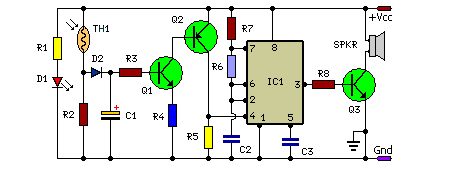
In this fire alarm circuit, a thermistor functions as the heat sensor. As the temperature rises, its resistance diminishes, and conversely, when the temperature falls, its resistance increases. At standard temperature, the resistance of the thermistor (TH1) is approximately...
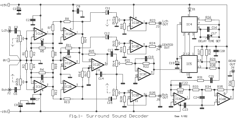
The circuit operation begins by transmitting stereo surround sound signal quality information through the master volume circuit. This drives the left channel connected to the LCH Model TL072 IC1A and IC1B, which are linked to the right channel (Rch)....
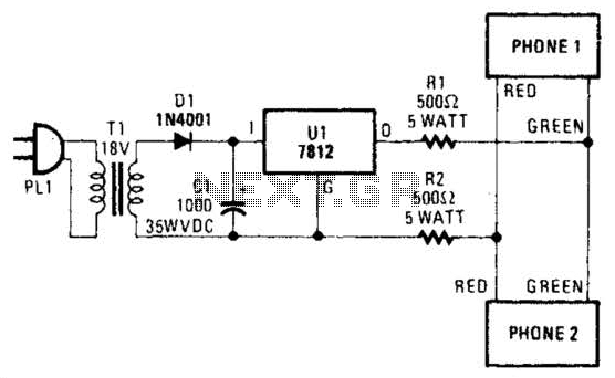
Two telephones can be used as an intercom by utilizing this circuit. Older style rotary phones that are non-electronic may be the most suitable for this application. Additionally, handsets alone can be powered in this manner. This intercom circuit allows...