
Automatic electrical circuit limit

The electric power limiter circuit is designed to enhance safety and efficiency in household electrical systems. The TWH8778 integrated circuit serves as the core component, which integrates both the current sensing and switching functionalities. This device can be configured to monitor the current flowing through the load, allowing users to set a specific current limit based on the requirements of their appliances.
The circuit typically includes a current transformer or a shunt resistor to measure the load current accurately. The output from this sensing element is fed into the TWH8778, which compares the measured current against the preset limit. If the current exceeds the defined threshold, the TWH8778 activates its internal relay or switch mechanism, effectively disconnecting the power supply to the load. This action protects appliances from potential damage due to overcurrent conditions and prevents excessive electricity consumption.
In addition to its protective functions, the circuit can incorporate visual indicators, such as LEDs, to provide real-time feedback to the user regarding the operational status of the load. For example, a green LED may indicate normal operation, while a red LED could signal an overload condition, prompting the user to investigate the issue.
The installation of this power limiter circuit is straightforward and can be integrated into existing electrical systems without significant modifications. It is essential to ensure that the circuit is rated appropriately for the expected load and that all components are installed in accordance with local electrical codes and standards to guarantee safe operation.
Furthermore, the automatic monitoring feature of this circuit allows for ongoing assessment of energy consumption, making it a valuable tool for users looking to manage their electricity usage more effectively. By limiting the current draw of connected appliances, the circuit contributes to energy conservation and can lead to reduced utility bills over time. Overall, the electric power limiter circuit represents a practical solution for enhancing the safety and efficiency of household electrical systems.Electric power limiter circuit limits the user load, making household appliances in a given normal operating current range when the load exceeds a given value, the power supply will be cut off. Heres a high-power integrated use TWH8778 automatic limit switch electrical appliances, which can be preset limit value of the load current, which is safe installed in the power line of the end user, the user can automatically monitor electricity consumption restrictions. The automatic limit electrical circuit from the power circuit, and a control circuit detects turtle road circuit,
Related Circuits
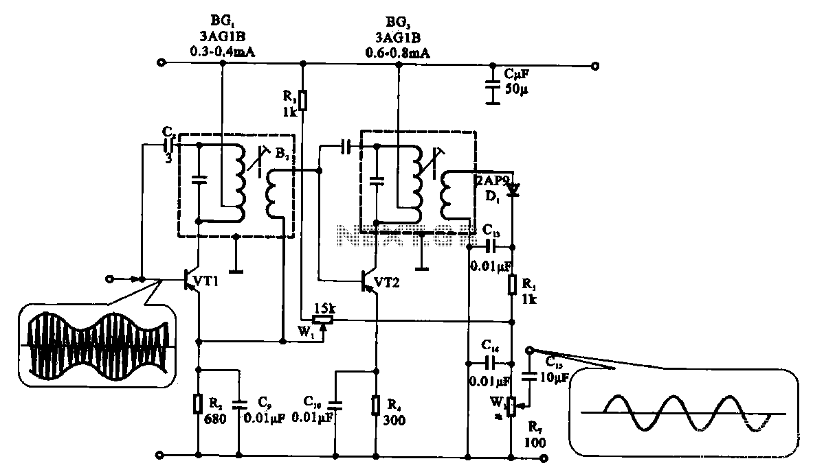
The demodulation and detection circuit is a radio AM intermediate frequency (IF) signal amplifier that performs two-stage detection using diode Dr. It extracts the audio signal from the IF carrier detection and subsequently sends it to the power amplifier...
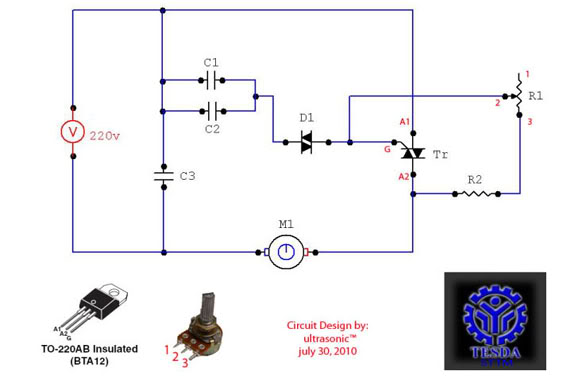
This circuit functions as a motor controller, allowing for easy control and variation of the RPM and phase of an AC motor. The power source is directly 220VAC, and it can handle a load of approximately 1 horsepower AC...
AVC - The circuit regulates the volume line automatically, providing an output voltage of approximately 4 volts peak to peak. This voltage remains consistent. The Automatic Volume Control (AVC) circuit is designed to manage audio levels dynamically, ensuring a stable...
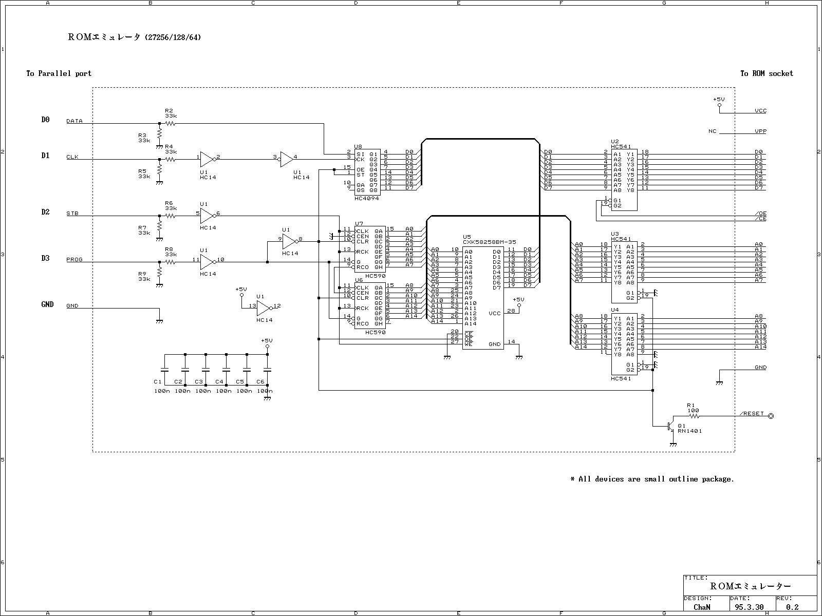
This ROM emulator improves the easiness to build/use it by reducing down its function which can be used as a ROM emulator. The kind of the ROM types to be emulated are 2764, 27128, and 27256. The debugging capability...
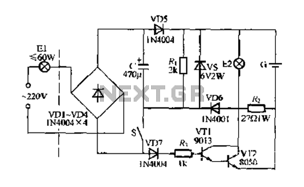
Figure 283 illustrates a blackout emergency lighting controller designed for straightforward external installation with two leads. This controller can directly replace the P Chan Tong Ge opening. Under normal power conditions, it functions like a conventional switch to control...
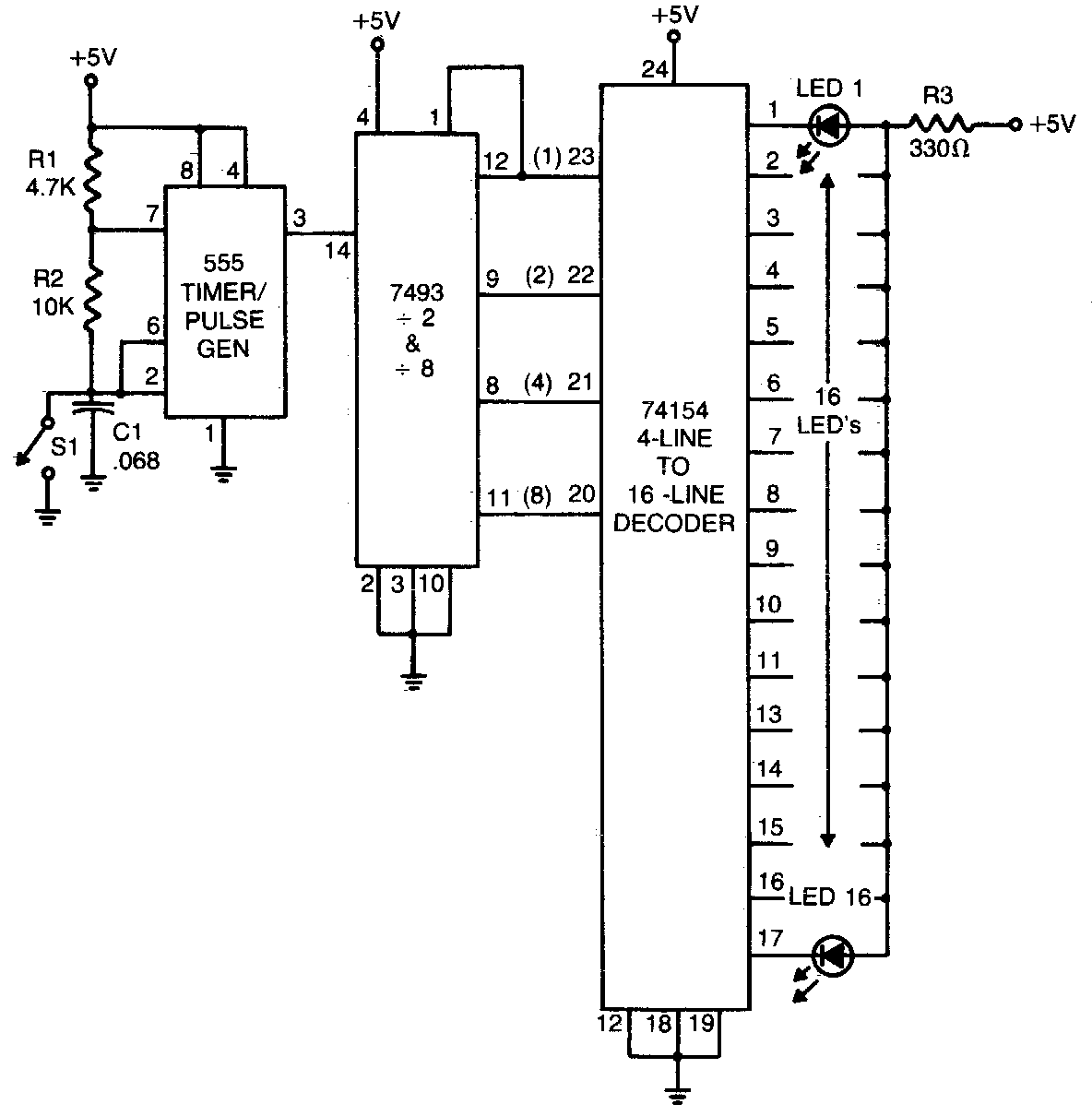
The 555 timer generates a rapid series of pulses when switch SI is open. These pulses are counted in groups of 16 and converted into binary form by the 7493, which is then fed into the 74154, a 1-of-16...