
Electric candle simulation schematic
More: How do we get the light off? Blow against the thermistor so that it cools, bladder, if necessary several times and the light goes out slowly. A thermistor has cooled a higher resistance, thus reducing the current passes through. This will also mean less power to the base of the transistor and hence the transistor. The light goes out. With the variable resistor, you can set the temperature at which the light will light. Turn the shaft of the potentiometer so that the light goes off. Wait until the thermistor cools down. Then turn the potentiometer until the lamp is lit, and then turn it right back so the light just goes out. Check the position of the lamp and the thermistor. The filament in the bulb should be as close to the thermistor are. R1 = 10kΩ NTC R2 = 2.2 kOhm P1 = 10 kOhm T1, T2 = BC548 La1 = 12 V/50 mA
The described circuit utilizes a thermistor, a type of temperature-sensitive resistor, to control the operation of a light bulb based on temperature changes. The thermistor (designated as R1, a 10 kΩ NTC) decreases in resistance when heated, which in turn affects the voltage across it. This decrease in resistance allows more current to flow into the base of the first transistor (T1, BC548), which is configured as a switch.
As the current increases at the base of T1, it turns on, allowing current to flow from the collector to the emitter, which in turn powers the second transistor (T2, also a BC548). The activation of T2 allows current to flow through the light bulb (La1, rated at 12 V and 50 mA), illuminating it. The positioning of the thermistor close to the light bulb ensures that the heat generated by the bulb can maintain the thermistor's temperature, keeping the circuit active as long as the heat is sufficient.
To turn off the light, one can blow on the thermistor, which cools it down and increases its resistance. This causes a reduction in current flowing to the base of T1, eventually turning it off, which also turns off T2 and the light bulb.
A variable resistor (P1, 10 kΩ) is included in the circuit to adjust the sensitivity of the thermistor. By turning the potentiometer, the threshold temperature at which the light turns on can be set. The process involves adjusting the potentiometer until the light turns on and then slightly turning it back to find the point where the light just goes off.
This circuit effectively demonstrates a simple thermal switch mechanism, where the light's operation is directly tied to the thermal response of the thermistor, mimicking the behavior of a candle being lit or extinguished through thermal energy. The careful arrangement of components ensures reliable operation and allows for user adjustment of the temperature threshold.For a candle to burn, we need a heat source (the flame of a match) and to extinguish it, you do it just to blow out. The following circuit behaves similarly. If you use your fingers heats the thermistor, its resistance decreases. The tension on the thermistor is lower and there is more current to the base of the left transistor. From here, more power to the base of the right transistor, which will guide and the light comes on. If the light and the thermistor close to each other, the heat of the thermistor heat lamp and the lamp will remain lit.
How do we get the light off? Blow against the thermistor so that it cools, bladder, if necessary several times and the light goes out slowly. A thermistor has cooled a higher resistance, thus reducing the current passes through. This will also mean less power to the base of the transistor and hence the transistor. The light goes out. With the variable resistor, you can set the temperature at which the light will light. Turn the shaft of the potentiometer so that the light goes off. Wait until the thermistor cools down. Then turn the potentiometer until the lamp is lit, and then turn it right back so the light just goes out.
Check the position of the lamp and the thermistor. The filament in the bulb should be as close to the thermistor are. R1 = 10k? NTC R2 = 2.2 kOhm P1 = 10 kOhm T1, T2 = BC548 La1 = 12 V/50 mA 🔗 External reference
Related Circuits
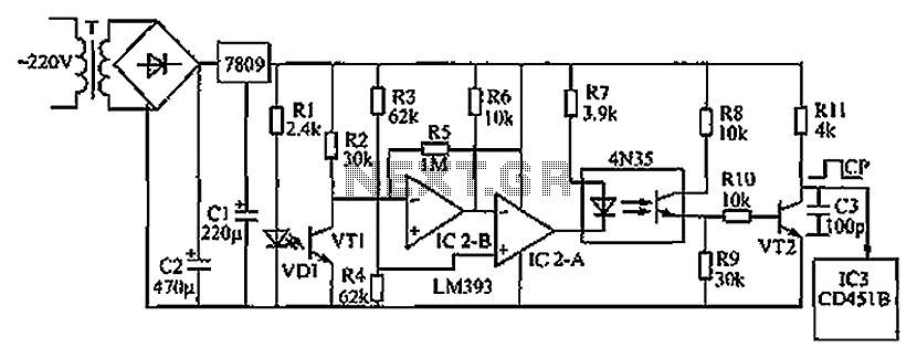
The circuit depicted in the figure operates as follows: when the phototransistor VT1 detects infrared light emitted by the infrared light-emitting diode, it enters a conductive state. This action causes the inverting input of comparator IC2-B, connected to pin...
This power supply circuit operates using 120 volts from household mains and should only be undertaken by individuals with the appropriate knowledge and skills to safely construct such a project. Failure to do so may result in personal injury...
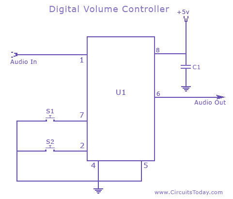
A digital volume control circuit diagram utilizing the DS1669, a potentiometer integrated circuit. This circuit can serve as a digital volume controller for audio amplifiers and various other applications. The digital volume control circuit employs the DS1669 integrated circuit, which...
The MT-2 Metal Zone™ is one of the most popular guitar pedals, delivering intense distortion tones characterized by pronounced mids and lows, along with an ultra-saturated sound. It features a distinctive dual-gain circuitry that enables long sustain and emphasizes...
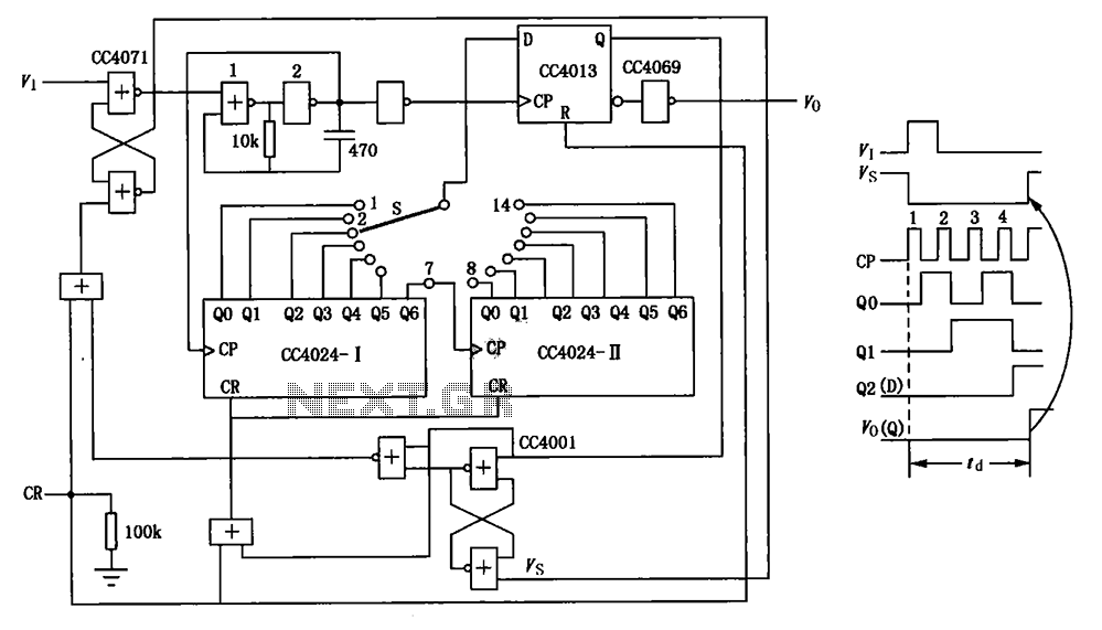
The circuit depicted in the figure is an optional delay circuit with a division factor. It consists of two 7-bit binary serial counters (CC4024) along with a controlled pulse source, which is composed of gate 1 and gate 2,...
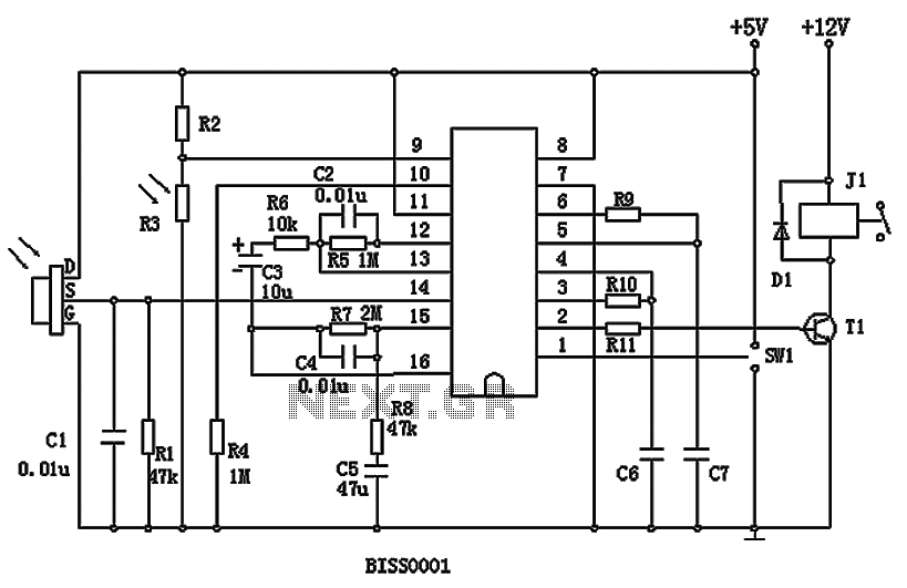
BISS0001 is a high-performance integrated circuit designed for sensor signal processing. It is used in conjunction with pyroelectric infrared sensors and requires only a few external components to function as a passive pyroelectric infrared switch. This circuit can automatically...
Warning: include(partials/cookie-banner.php): Failed to open stream: Permission denied in /var/www/html/nextgr/view-circuit.php on line 713
Warning: include(): Failed opening 'partials/cookie-banner.php' for inclusion (include_path='.:/usr/share/php') in /var/www/html/nextgr/view-circuit.php on line 713