
Pyroelectric infrared processing chip BISS0001 and pyroelectric elements D204B
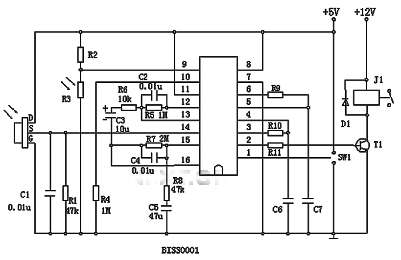
The circuit comprises an operational amplifier (OP1) that serves as the first stage amplifier for the pyroelectric infrared sensor. The output signal from OP1 is coupled through capacitor C3 to a second operational amplifier (OP2), which acts as the second stage amplifier. The processed signal is then fed into a two-way amplitude voltage comparator (COP1 and COP2), which generates an effective detection trigger signal (Vs) to initiate a delay timer. The output signal (Vo) is amplified by transistor T1, which in turn activates a relay load.
In the circuit, R3 functions as a photosensitive resistor that detects ambient light levels. When used for lighting control, an increase in environmental brightness reduces the resistance of R3, causing input pin 9 to be held low and thereby blocking the trigger signal (Vs). The work mode selection switch (SW1) allows for two operational modes: when connected to one terminal, the chip operates in a retriggerable mode; when connected to the other terminal, it operates in a non-retriggerable mode. Resistor R6 can be adjusted to alter the gain of the amplifier; the original design specifies a value of 10K, but a value of 3K can be used to enhance circuit performance. The output delay time (Tx) is determined by external components R9 and C7, while the blocking time (Ti) is set by R10 and C6. A standard value of 470 ohms may be used for R9 and R10, with C6 and C7 typically set to 0.1 µF.
The BISS0001 circuit is ideal for applications requiring reliable motion detection and automatic control, providing flexibility and efficiency in various environments. The integration of pyroelectric sensors with minimal external components simplifies installation and maintenance, making it an excellent choice for both commercial and residential use. BISS0001 is a sensor signal processing integrated circuit with higher performance, it is accompanied pyroelectric infrared sensors and a small amount of external components con stitute passive pyroelectric infrared switch. It can automatically and quickly open various types of incandescent, fluorescent, buzzer, automatic doors, electric fans, dryers and automatic sinks and other devices, especially for enterprises, hotels, shopping malls, warehouses and family aisles, corridors and other sensitive area, or automatic lighting, lighting and alarm systems for the security zone. The figure above, the output signal of the operational amplifier OP1 pyroelectric infrared sensor as the first stage amplifier, and then by the C3 coupled to the operational amplifier OP2 for the second stage amplifier, and then through the two-way amplitude voltage comparator COP1 and COP2 constituted after the treatment, the effective detection trigger signal Vs to start delay timer, the output signal Vo amplification by the transistor T1 is turned on to drive a relay load.
The figure above, R3 is photosensitive resistance, to detect environmental illumination. When used as lighting control, if the environment brighter, the resistance value of R3 will be reduced, so that the input pin 9 is held low, thereby blocking the trigger signal Vs. SW1 is a work mode selection switch SW1 when communicating with an end when the chip is re-trigger work; when SW1 in communication with the second end, the chip is at the non-repeatable trigger work.
FIG R6 can adjust the size of the gain of the amplifier, the original drawings selected 10K, actual use can 3K, can improve the gain of the circuit to improve circuit performance. Output delay time Tx by an external R9 and sizing C7 triggered by an external blocking time Ti R10 and C6 resizing, R9/R10 470 ohms may be used, C6/C7 can choose 0.1U.
Related Circuits
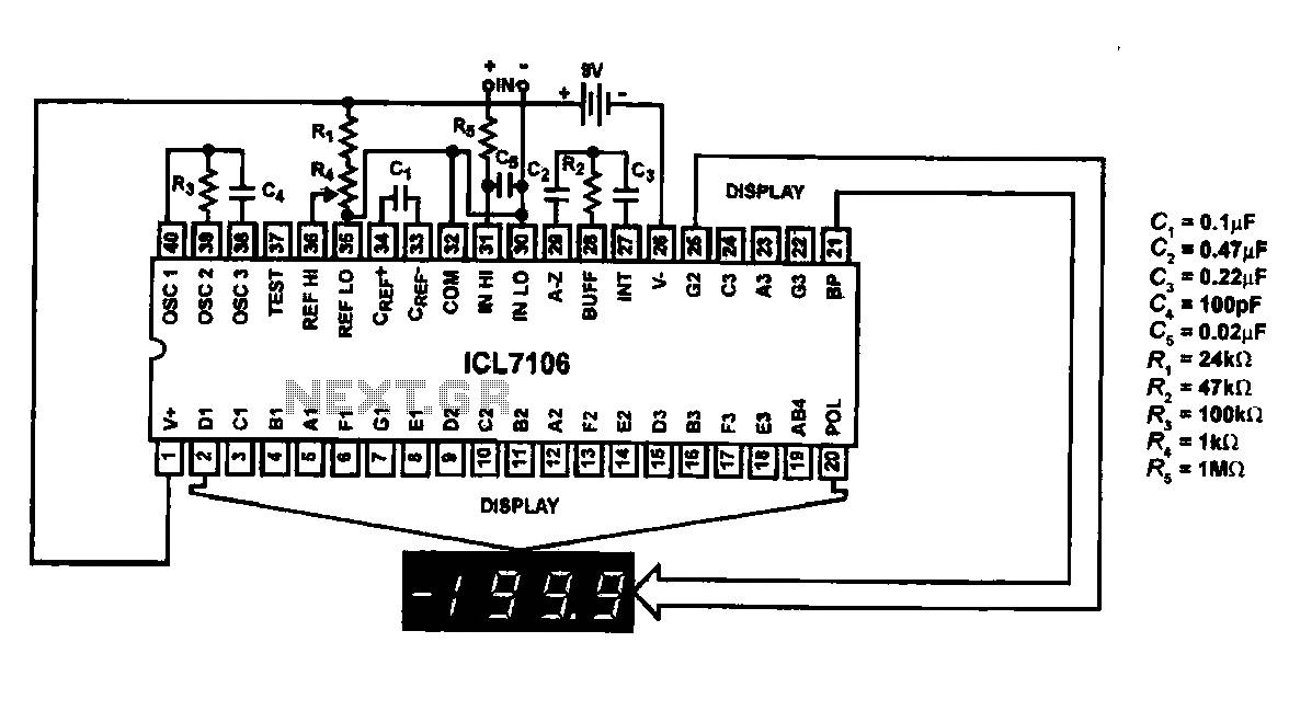
This circuit utilizes the ICL7106 / ICL7107 chip to drive a liquid crystal display (LCD). In this configuration, the ICL7106 / ICL7107 functions as a signal measurement and analog-to-digital (A/D) converter. It detects an analog input signal, amplifies it,...

The infrared transmitter and receiver circuit depicted in the schematic diagram below can function as a remote control. The transmitter primarily operates as an oscillator. The infrared transmitter and receiver circuit is designed to facilitate wireless communication through infrared signals,...

The circuit utilizes an integrated amplifier, resulting in a simple and compact design. The TDA4050 IC is employed, where a weak signal is received by the infrared photodiode (VD) and first passes through a transistor amplifier. The circuit is...

The circuit utilizes a tuned circuit for frequency selection, designed to operate at approximately 51 kHz. The 2N3565 transistor amplifies the output generated by the tuned circuit. The described circuit operates on the principle of resonance, where the tuned circuit...

The infrared (IR) toggle switch project described here aims to provide a control mechanism for electrical appliances that lack remote operation features. The goal is to construct a black box where users can plug in their 120V AC appliance...
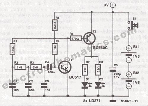
This infrared transmitter is designed for use with an infrared receiver. It operates using either two 1.5V batteries or a 3V lithium battery, allowing for a compact infrared communication system. The infrared transmitter circuit typically consists of an infrared LED,...