
Electric Guitar Preamplifier
The first section of the preamplifier circuit is a single-transistor common-emitter amplifier with degenerative feedback in the emitter and a boot-strapped bias divider to ensure optimal input impedance. With the specified component values, the input impedance exceeds 50 kilo-ohms, and the peak output voltage is approximately 2V RMS. The master-level-control potentiometer, VR1, should be adjusted to minimize distortion. The input from the guitar pickup connects to the preamplifier at terminal J1. The signal is buffered and processed by an operational amplifier circuit built around IC TL071 (IC1). The gain can be adjusted using the preset potentiometer, VR2. The circuit includes both a master and a slave control. RCA socket J2 serves as the master signal output, while socket J3 functions as the slave output. It is preferable to use the signal from J2 as the input to the power amplifier system or sound mixer, while output signals from J3 can drive a standard headphone amplifier. The slave output level at J3 can be adjusted using potentiometer VR3.
The entire circuit should be housed in a metallic case, with VR1 and VR3 ideally being types with metal enclosures to reduce interference. To mitigate hum, it is essential to ground both the case and the enclosures. A well-regulated 9V DC power supply is critical for the operation of this circuit, although a standard 9V alkaline manganese battery can also be utilized. The circuit includes a power on/off switch, denoted as S1.
This guitar preamplifier circuit effectively amplifies the weak electrical signals generated by the pickups, ensuring high fidelity and low noise for subsequent audio processing. The use of a common-emitter amplifier configuration provides significant voltage gain, while the operational amplifier stage allows for flexible gain adjustment and buffering, maintaining signal integrity. The dual output configuration enhances versatility, accommodating different audio equipment setups. Proper grounding and shielding measures are integral to minimizing electromagnetic interference, ensuring optimal performance in various environments.Here is the circuit diagram of a guitar preamplifier that would accept any standard guitar pickup. It is also versatile in that it has two signal outputs. A typical example of using a pick-up attached to a guitar headstock is shown in Fig. 1. The pickup device has a transducer on one end and a jack on the other end. The jack can be plugged into a preamplifier circuit and then to a power amplifier system. The pickup device captures mechanical vibrations, usually from stringed instruments such as guitar or violin, and converts them into an electrical signal, which can then be amplified by an audio amplifier. It is most often mounted on the body of the instrument, but can also be attached to the bridge, neck, pick-guard or headstock.
The first part of this preamplifier circuit shown in Fig. 2 is a single-transistor common-emitter amplifier with degenerative feedback in the emitter and a boot-strapped bias divider to secure optimal input impedance. With the component values shown here, the input impedance is above 50 kilo-ohms and the peak output voltage is about 2V RMS.
Master-level-control potentiometer VR1 should be adjusted for minimal distortion. The input from guitar pickup is fed to this preamplifier at J1 terminal. The signal is buffered and processed by the op-amp circuit wired around IC TL071 (IC1). Set the gain using preset VR2. The circuit has a master and a slave control. RCA socket J2 is the master signal output socket and socket J3 is the slave. It is much better to take the signal from J2 as the input to the power amplifier system or sound mixer. Output signals from J3 can be used to drive a standard headphone amplifier. Using potentiometer VR3, set the slave output signal level at J3. House the circuit in a metallic case. VR1 and VR3 should preferably be the types with metal enclosures. To prevent hum, ground the case and the enclosures. A well-regulated 9V DC power supply is crucial for this circuit. However, a standard 9V alkaline manganese battery can also be used to power the circuit. Switch S1 is a power on/off switch. 🔗 External reference
Related Circuits

For the DIY Motion Platform III, the electrical motion drive was expanded to three channels. The small signal concept remained unchanged, but the MOSFET half-bridge was modified to a full bridge (H-bridge). The DAC converter was upgraded to a...
The following presents an electrical schematic for a 1993 VW Passat. Features include vehicle content and electrical wiring schematic. Components consist of console switches, electric windows, ABS control unit, ABS hydraulic unit, engine control module, automatic control unit, fuse/relay...
Both transistors should be low noise types. In the original circuit, BC650C was used, which is an ultra-low noise device. These transistors are now hard to find, but BC549C or BC109C are good replacements. The circuit is self-biasing and...
The preamplifier is designed for use with dynamic (moving coil, MC) microphones that have an impedance of up to 200 ohms and feature balanced terminals. It is relatively straightforward. The preamplifier circuit serves as a crucial interface between the microphone...
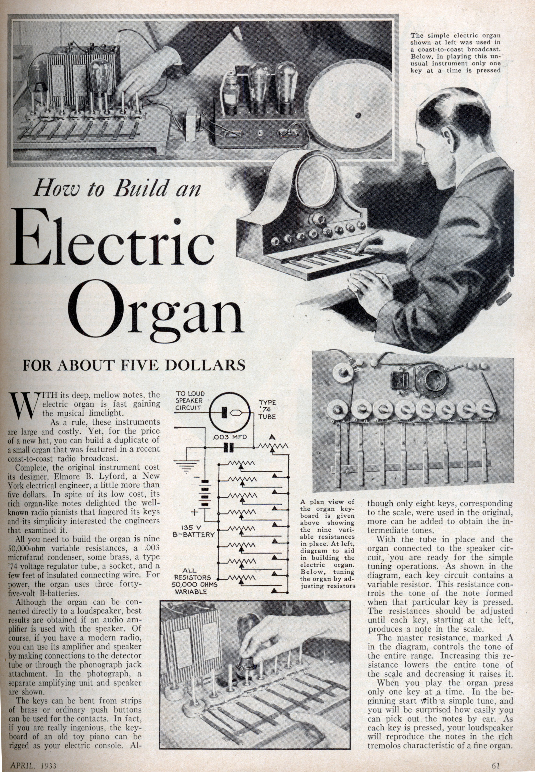
With its deep, mellow tones, the electric organ is rapidly gaining popularity in the music scene. Typically, these instruments are large and expensive. However, for the price of a new hat, one can construct a miniature version of an...
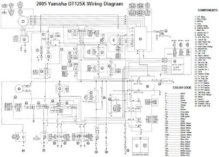
The electrical system of the 2005 Yamaha DT125X typically includes a CDI unit, battery, thermo unit, rectifier/regulator, servomotor, fuse, neutral switch, ignition coil, and main switch. The electrical schematic for the 2005 Yamaha DT125X outlines the interconnections and functionalities...
Warning: include(partials/cookie-banner.php): Failed to open stream: Permission denied in /var/www/html/nextgr/view-circuit.php on line 713
Warning: include(): Failed opening 'partials/cookie-banner.php' for inclusion (include_path='.:/usr/share/php') in /var/www/html/nextgr/view-circuit.php on line 713