
2005 Yamaha DT125X Wiring Diagram Electrical Schematic
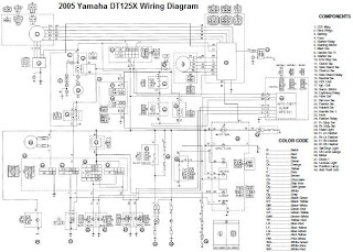
The electrical schematic for the 2005 Yamaha DT125X outlines the interconnections and functionalities of the various components that comprise its electrical system. The CDI (Capacitor Discharge Ignition) unit plays a crucial role in the ignition system by controlling the timing and intensity of the spark delivered to the ignition coil. This component is essential for the efficient operation of the engine, as it ensures optimal combustion.
The battery serves as the primary power source for the electrical system, providing the necessary voltage for starting the engine and powering auxiliary systems such as lights and indicators. The thermo unit monitors the engine temperature, providing critical data to prevent overheating and ensuring the engine operates within safe temperature limits.
The rectifier/regulator is responsible for converting the AC voltage generated by the alternator into DC voltage suitable for charging the battery and powering the electrical components. This unit ensures that the voltage levels remain stable, preventing damage to sensitive electronic components.
The servomotor is typically involved in controlling various mechanical functions, such as throttle position or other actuators, allowing for responsive adjustments based on input from the rider or the vehicle's control systems. The fuse provides overcurrent protection, safeguarding the electrical system from potential damage due to short circuits or overloads.
The neutral switch is a safety feature that indicates whether the transmission is in neutral, preventing accidental starts when the bike is in gear. The main switch controls the overall power to the electrical system, allowing the rider to turn the system on or off as needed.
Overall, the electrical system of the 2005 Yamaha DT125X is designed to provide reliable performance, ensuring that all components work together seamlessly for optimal operation of the motorcycle. Proper understanding of the schematic is essential for troubleshooting and maintenance of the system.Usually, the electrical system of the 2005 Yamaha DT125X consists of CDI unit, battery, thermo unit, rectifier/regulator servomotor, fuse, neutral switch, ignition coil and main switch. (click image to enlarge) 🔗 External reference
Related Circuits
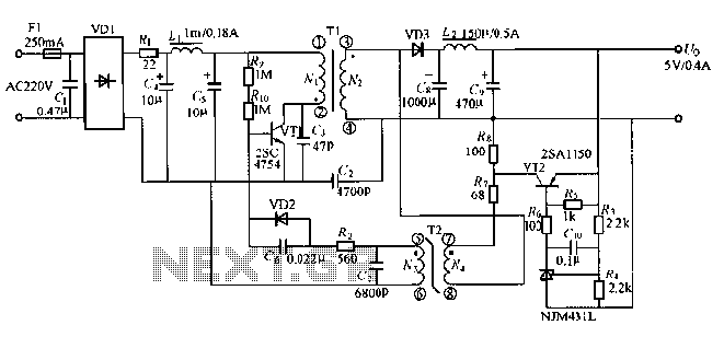
The output displays a 5V / 0.4A low-power switching power supply circuit, which can be utilized to create a transformer saturation soft-switching circuit. This low-power switching power supply circuit is designed to provide a stable 5V output at a current...
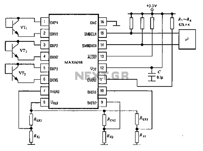
The circuit illustrated in the figure involves the MAX6698 maximum temperature sensor, which utilizes three transistors (VT1 to VT3) and three thermistors (RT1 to RT3). An internal reference voltage source is connected through resistors UREF REX1 to REX3, providing...
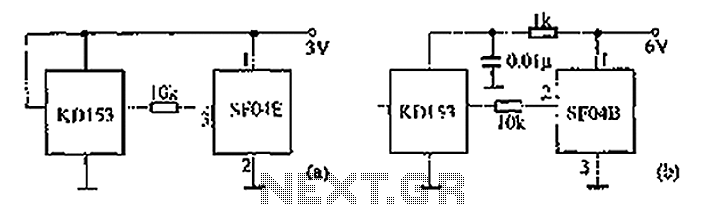
The circuit diagram illustrates the SF04E emission and the corresponding SF04B. Part (A) depicts the composition of the remote control transmitter SF04E, along with its compatible receiving circuit, which can be assembled using the SJ04H. Part (B) presents the...
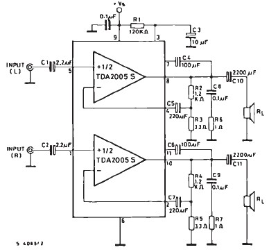
The TDA2005 car audio amplifier circuit is specifically designed for use in devices such as car radios and CD players. This amplifier circuit utilizes the TDA2005 audio integrated circuit (IC), which can deliver a maximum output power of 20...

Music Driven Motor Schematic. The geared motor drives the stem of a dancing flower to the beat of music. The music-driven motor schematic involves a geared motor that is activated in response to sound signals, specifically music. This design typically...
The roles of capacitors C1, C4, and C5 in a circuit may not be immediately clear. Capacitors on the power rail help to smooth out the signal by reducing current ripple, which can be observed using an oscilloscope. Resistors...
Warning: include(partials/cookie-banner.php): Failed to open stream: Permission denied in /var/www/html/nextgr/view-circuit.php on line 713
Warning: include(): Failed opening 'partials/cookie-banner.php' for inclusion (include_path='.:/usr/share/php') in /var/www/html/nextgr/view-circuit.php on line 713