
Electric shaver motor drive circuit

The electric shaver motor drive circuit is designed to efficiently manage the charging and operation of the motor using an AC voltage of 220V. The circuit typically includes a rectifier to convert the AC input into a DC voltage suitable for battery charging. This rectified voltage is then regulated to ensure that the battery receives a stable and appropriate charging current, preventing overcharging and extending battery life.
The inclusion of a charge-on switch (K) allows the user to control the activation of the motor. When the switch is closed, it completes the circuit, enabling the power supply to the motor. The motor is often equipped with a controller or driver circuit to manage its speed and torque, ensuring optimal performance during operation.
Additional components may include fuses for overcurrent protection, capacitors for filtering and smoothing the power supply, and diodes for preventing back EMF generated by the motor from damaging the circuit. The design may also incorporate a thermal cutoff switch to protect against overheating, ensuring safety during prolonged use.
Overall, this circuit design emphasizes reliability and user control, making it suitable for use in consumer electric shavers, where performance and safety are paramount.Electric shaver motor drive circuit It shows a typical motor drive circuit of an electric shaver. AC 220V to charge the battery through the charging circuit, but also for the m otor power supply. After the charge-on switch K, the motor can work.
Related Circuits

This design circuit features a simple, cost-effective amplitude-stabilized phase-shift sine wave oscillator that requires one integrated circuit (IC) package, three transistors, and operates from a single power supply. The circuit incorporates an RC network configured for phase shift, oscillating...

This compact water sensor alarm circuit emits a loud warning sound when a humidity sensor detects the presence of water. The circuit utilizes the low-power comparator LM1801 from National Semiconductor. A fixed reference voltage for the integrated circuit is...

The circuit is straightforward yet capable of outstanding performance. It has been specifically designed as an amplifier for the digital sound card in a computer. Audio input can be sourced from any two-channel line-level device such as a television,...

The metal detector circuit is presented here, illustrating a simple yet effective design. It utilizes a 40, 106 Hex Schmitt inverter IC, a capacitor, a search coil, and batteries. An advantage of connecting IC1b Pin 4 to a medium-wave...
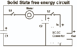
It's very simple actually. The idea is that we use what we have learned from the capacitor tests to create a circuit that uses the capacitors to run the load and then by discharging the 1/2 full capacitor into...
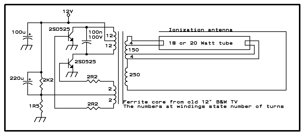
Whenever there is a need for battery-powered lighting, such as for camping, solar-powered cottages, cars, boats, planes, or emergency situations, fluorescent lamps are highly appealing. They are significantly more efficient than incandescent lamps, producing much more light for less...
Warning: include(partials/cookie-banner.php): Failed to open stream: Permission denied in /var/www/html/nextgr/view-circuit.php on line 713
Warning: include(): Failed opening 'partials/cookie-banner.php' for inclusion (include_path='.:/usr/share/php') in /var/www/html/nextgr/view-circuit.php on line 713