
nicola teslas electric car revealed
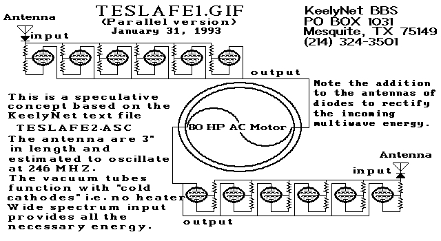
The provided schematic diagrams depict two fundamental configurations of electrical circuits: a series circuit and a parallel circuit, both incorporating the 70L7GT Half Wave Rectifier. This rectifier is a crucial component in converting alternating current (AC) to direct current (DC), allowing for the effective utilization of electrical energy in various applications.
In the series circuit configuration, the rectifier is connected in a single path with other components such as resistors and capacitors. This arrangement ensures that the same current flows through all components, making it suitable for applications where a consistent current is required. The voltage across each component can vary, but the total voltage is the sum of the individual voltages. This characteristic can be advantageous in specific scenarios where voltage division is necessary.
Conversely, the parallel circuit configuration allows the rectifier to be connected alongside other components, providing multiple paths for current to flow. In this setup, each component experiences the same voltage, which can be beneficial for applications requiring stable voltage across components. The total current flowing through the circuit is the sum of the currents through each parallel branch, which can enhance the overall current capacity of the circuit.
The 70L7GT Half Wave Rectifier is notable for its robust performance in low-power applications. Its ability to handle moderate voltage levels makes it suitable for various experimental setups, particularly for those interested in exploring Tesla's historical experiments with electrical circuits. For individuals with limited budgets, acquiring a small quantity of these tubes for experimentation can yield valuable insights into their performance characteristics and potential applications.
In conclusion, the schematic diagrams serve as a foundation for understanding the operational principles of series and parallel circuits utilizing the 70L7GT Half Wave Rectifier. Further experimentation with these circuits can lead to a deeper comprehension of their functionality and practical applications in electronics.There are two schematic diagrams showing a series and a parallel circuit that Tesla could have used. The tubes used were a common 70L7GT Half Wave Rectifer that believe it or notare still available today. I know all of you want to see this site but be patient. Here are the circuit diagrams: Just a suggestion I personally would buy only a couple of these tubes and experiment to see what kind of output that you could
expect to see. I personally have a very limited experimental budget and thus can not experiment as extensively as I would like. Here are some images of the tube. 🔗 External reference
Related Circuits
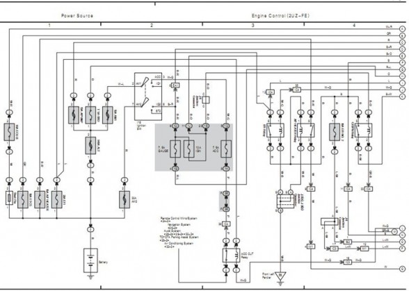
The following circuit illustrates the electrical circuit diagram for the 2006 Toyota 4Runner. It includes specifications related to the Toyota vehicle and details on safety features. The electrical circuit diagram of the 2006 Toyota 4Runner serves as a comprehensive representation...
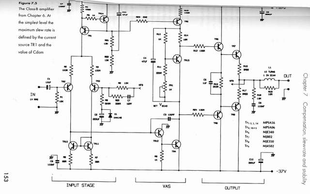
This article is intended for individuals interested in constructing their own car amplifier. The fundamental calculations will be discussed below. Understanding these concepts will enable the construction of a car amplifier independently. The challenge in designing a car power...
The circuit is a comparator that measures the voltage of a car battery in steps of 1 Volt. The voltage measurement is performed by comparing the battery voltage, applied to the inverting inputs of amplifiers, against reference voltages produced...
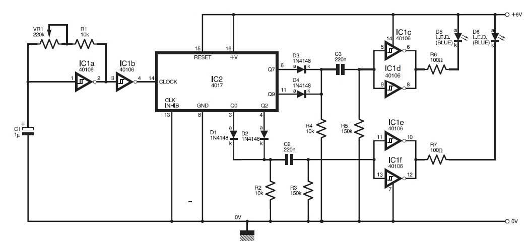
This circuit simulates the flashing lights of a police car, similar to those seen on British police vehicles. The operational amplifier IC1a functions as a square wave oscillator, with an adjustable frequency controlled by the variable resistor VR1 to...
This simple circuit drives six LEDs in a Knight Rider scanner mode. Power consumption primarily depends on the type of LEDs used, especially when utilizing a 7555 (555 CMOS version). The Knight Rider scanner circuit is designed to create a...
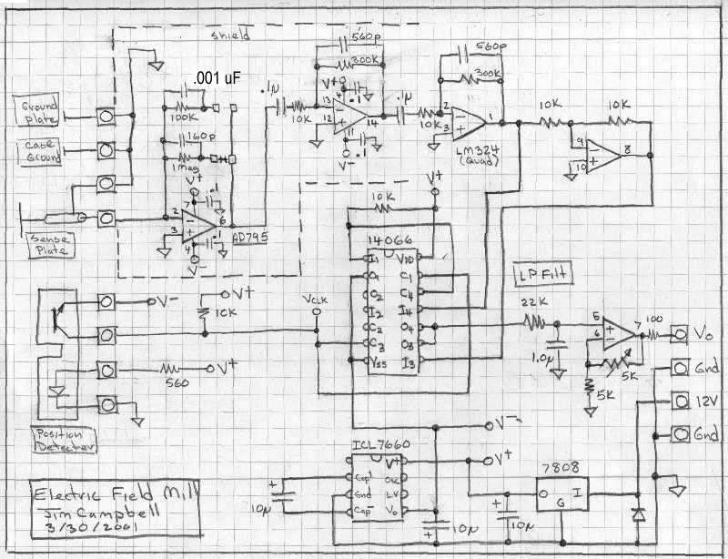
This page outlines the construction of an electric field mill, a device used to measure the electric field strength on Earth due to static electric fields and the charge of clouds overhead. It can also investigate the effects of...