
Honda CB750 Electrical
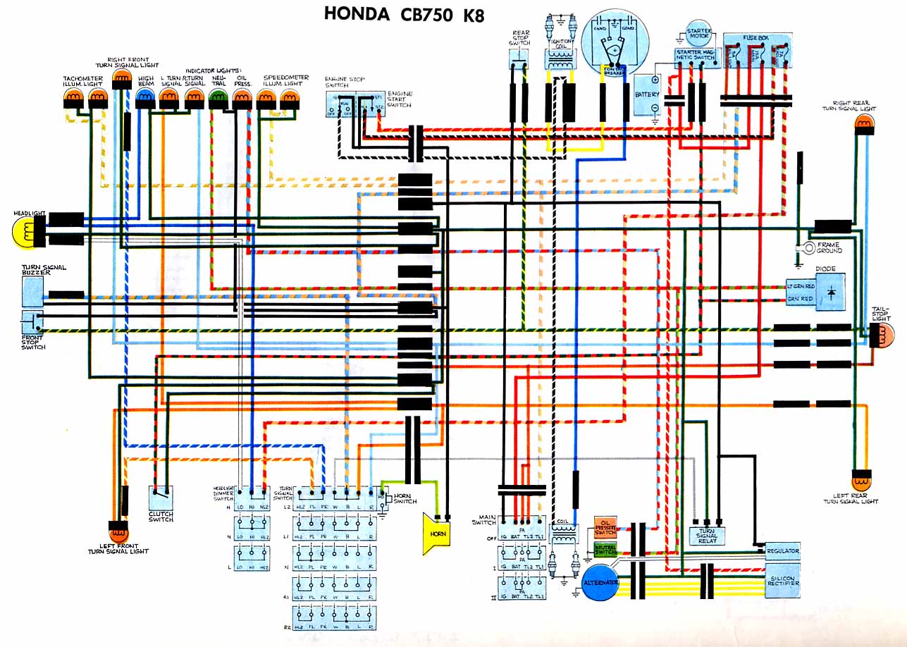
The Honda CB750 electrical circuit diagram is designed to facilitate the understanding and troubleshooting of the motorcycle's electrical system. This circuit encompasses several critical components that contribute to the overall functionality of the vehicle.
The turn signal relay is an essential part of the signaling system, allowing for the activation and deactivation of the turn signals when the rider engages the corresponding switch. This relay ensures that the turn signals operate in a timed sequence, providing clear indications to other road users.
The oil pressure switch is a safety feature that monitors the engine's oil pressure. If the oil pressure drops below a certain threshold, the switch activates a warning light on the dashboard, alerting the rider to potential issues that could lead to engine damage. This component is vital for maintaining engine health and longevity.
The neutral switch serves to indicate when the motorcycle is in neutral gear. This switch is crucial for starting the engine, as it prevents the engine from being started while in gear, thereby enhancing rider safety. When the transmission is in neutral, the switch closes the circuit, allowing the starter motor to engage.
In addition to these components, the circuit also includes various fuses, connectors, and wiring harnesses that interconnect the electrical system, ensuring reliable operation of all electrical functions. The schematic provides a visual representation of these connections, which is invaluable for maintenance and repair tasks. Understanding this electrical circuit diagram is essential for technicians and enthusiasts alike, enabling effective troubleshooting and modifications to the Honda CB750's electrical system.The following circuit shows about Honda CB750 Electrical Circuit Diagram. Features: turn signal relay, oil pressure switch, neutral switch, .. 🔗 External reference
Related Circuits
The equation is as follows: If a circuit has a resistance of 25 ohms and a potential of 125 volts, the current drawn in this circuit would be 5 amps. This basic circuit provides a foundational understanding for the...
Over time, various factors can lead to electrical issues in a Mustang. Components may become old and worn, or a wire might rub against something, exposing it to metal. Instances have been observed where body shops inadvertently crimp wires...
The following page outlines detailed information and the schematic of the 1985 Pontiac Fiero Wiring Diagram and Electrical System. The electrical system consists of: The 1985 Pontiac Fiero features a complex electrical system designed to support various components and functionalities...
This circuit is designed to detect electrical wires connected to the mains (live wire). It features an LED for visual indication and a buzzer for audio alerts. As the detector is brought closer to the electrical wire, the LED...
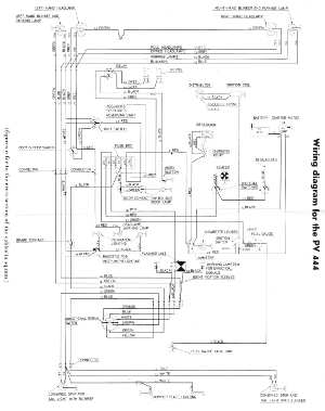
The following circuit illustrates the wiring diagram for the Volvo PV444, a vintage car electrical circuit. It provides an electrical understanding of this uni-body vehicle. The Volvo PV444 wiring diagram serves as a crucial reference for understanding the electrical system...
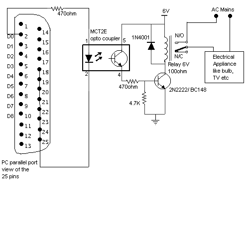
Control electrical appliances using a PC. This circuit utilizes the printer port of a PC for control applications through software and some interface hardware. The interface circuit is included. The described circuit leverages the parallel printer port (also known as...
Warning: include(partials/cookie-banner.php): Failed to open stream: Permission denied in /var/www/html/nextgr/view-circuit.php on line 713
Warning: include(): Failed opening 'partials/cookie-banner.php' for inclusion (include_path='.:/usr/share/php') in /var/www/html/nextgr/view-circuit.php on line 713