
Electrification Circuit Unit
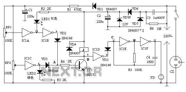
The circuit operates on the principle of energy transfer between the capacitor and the transformer, utilizing the characteristics of the thyristor for switching. The design emphasizes safety by ensuring that the high-voltage pulses are generated and controlled in a manner suitable for experimentation without risk. The use of a Schmitt trigger allows for clean transitions and pulse shaping, which is critical for the reliable operation of the thyristor. The resonant circuit formed by the transformer and capacitor C2 enhances the efficiency of energy transfer, allowing for effective high-voltage pulse generation. The careful selection of component values is crucial to achieving the desired PRF and pulse width, ensuring that the circuit performs as intended while maintaining operational safety.Here`s a design circuit that is intended for carrying out harmless experiments with high-voltage pulses and functions in a similar way as an electrified fence generator. The p. r. f. (pulse repetition frequency) is determined by the time constant of network R1-C3 in the feedback loop of op amp IC1a: with values as specified, it is about 0.
5 Hz. The stage following the op amp, IC1b, converts the rectangular signal into narrow pulses. Differentiating network R2-C4, in conjunction with the switching threshold of the Schmitt trigger inputs of IC1b, determines the pulse period, which here is about 1. 5 ms. The output of IC1b is linked directly to the gate of thyristor THR1, so that this device is triggered by the pulses.
Here`s the figure of the schematic diagram; The requisite high voltage is generated with the aid of a small mains transformer, whose secondary winding is here used as the primary. This winding, in conjunction with C2, forms a resonant circuit. Capacitor C3 is charged to the supply voltage (12 V) via R3. When a pulse output by IC1b triggers the thyristor, the capacitor is discharged via the secondary winding.
The energy stored in the capacitor is, however, not lost, but is stored in the magnetic field produced by the transformer when current flows through it. When the capacitor is discharged, the current ceases, whereupon the magnetic field collapses. This induces a counter e. m. f. in the transformer winding which opposes the voltage earlier applied to the transformer. This means that the direction of the current remains the same. However, capacitor C2 is now charged in the opposite sense, so that the potential across it is negative.
When the magnetic field of the transformer has returned the stored energy to the capacitor, the direction of the current reverses, and the negatively charged capacitor is discharged via D1 and the secondary winding of the transformer. As soon as the capacitor begins to be discharged, there is no current through the thyristor, which therefore switches off.
When C2 is discharged further, diode D1 is reverse-biased, so that the current loop to the transformer is broken, whereupon the capacitor is charged to 12 V again via R3. At the next pulse from IC1b, this process repeats itself. 🔗 External reference
Related Circuits
A 2002 Blazer was diagnosed with error codes P0155 and P0756, indicating a malfunction in the O2 sensor heater circuit and a performance issue with the shift solenoid B circuit. The vehicle initially has power, but it loses power...
The alarm protection can trigger a sound and light alert when the mains voltage exceeds or falls below a predetermined threshold. It automatically disconnects the electrical power supply without damaging the electrical protection. The device is compact, fully featured,...
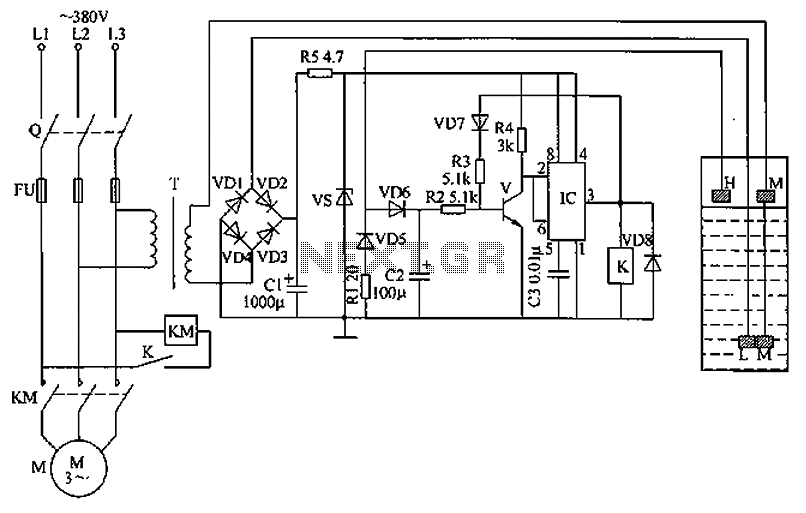
The circuit functions as a liquid level automatic controller, comprising a power circuit, a level detection circuit, and a control execution circuit. The power circuit includes a knife switch (Q), fuse (FU), power transformer (T), rectifier diodes (VD1 to...
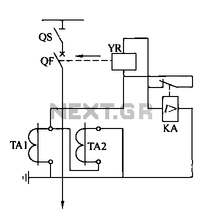
Operating power protection devices can be categorized into two types: DC power supply operation and AC operation. AC operating power is favored due to its lower investment costs, simpler operation, and reliable secondary circuit maintenance, making it widely used...
The circuit is a rechargeable short delay control for a conducting pipe, featuring two adjustment potentiometers (RP) that enable the delay time to be set from several hundred milliseconds to several seconds. The rechargeable short delay circuit is designed for...
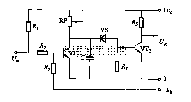
The south circuit consists of four parts, arranged in descending order: an NPN transistor dynamic garbage device (T1), a PNP transistor differential amplifier (T2, T3) forming a double differential circuit, two balanced output amplifiers with opposite phase, and a...