
555 circuits 6
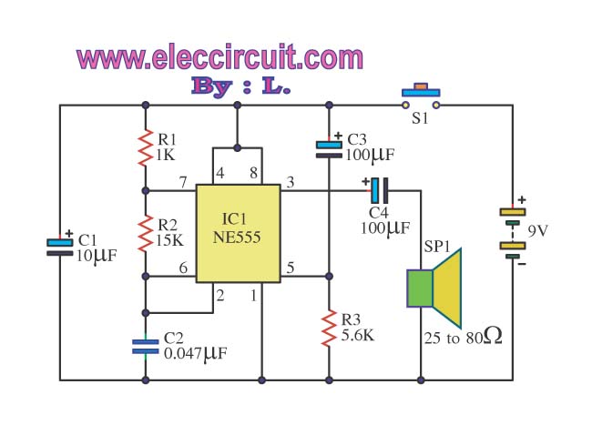
This circuit operates on the principle of using the 555 timer IC in various configurations to create timed events and sound generation. The primary function is to provide a delayed action for lamp control, allowing users to switch off the light without immediate disruption. The use of capacitors for noise filtering ensures stable operation, while the inclusion of transistors for audio output enhances the overall functionality. The design allows for flexibility in power supply options and provides a practical solution for everyday applications, such as lighting control and sound generation, thus enhancing user convenience and efficiency. The circuit can be adapted for various uses, making it a versatile addition to electronic projects.The heart of this circuit is IC No. 555. When the alert sound was working, even though the switch will continue to be the same, the sound still does not stop immediately. But it will stops automatically, when a set time period, Depending on the resistance of R3, the circuit so I set a time period equal to 1M for 1 minute 6 seconds.
The output of IC 555 is triggered by a positive voltage on pin 2, when all switches are connected together. When the something switch is cut off pin 2, it will be negative voltage and the trigger IC 555 will stop. The C1, C4 to protects a noise signal from either switch, which may cause the alarm to be up. This circuit can be used with power supply from 5V to 15V depending on relay sure enough. This circuit is intended to let the user turn off a lamp by means of a switch placed far from bed, allowing him enough time to lie down before the lamp really switches off.
Obviously, users will be able to find different applications for this circuit in order to suit their needs. Due to the low current drawing, the circuit can be supplied from 230Vac mains without a transformer. Supply voltage is reduced to 10Vdc by means of C1 reactance, a two diode rectifier cell D1 & D2 and Zener diode D3.
IC1 is a CMos 555 timer wired as a monostable, providing 15 seconds on-time set by R3 & C4. When SW1 is closed, IC1 output (pin 3) is permanently on, driving Triac D4 which in turn feeds the lamp. Opening SW1 operates the monostable and, after 15 seconds, pin 3 of IC1 goes low switching off the lamp Operation of the circuit is when the power supply to the circuit.
It will give birth to high frequency by using a circuit IC1 to a multi-state Devices Bill Brett Foster. The frequency with which R1, C1 and C2. The frequency will be out in three legs. And will be expanded with the IC2 output pin out of 5 in order to drive the speakers. The high-frequency sound. But when the switch S1, capacitor. C1, which continue to cycle in a manner parallel to the C2 value higher density. IC1 will give birth to low-frequency out of pin 3 to IC2 then drive the speakers. This circuit can cause the audio source has two frequency When the power supply input to IC1 is the output pin 3 at a frequency of 1 kHz.
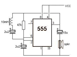
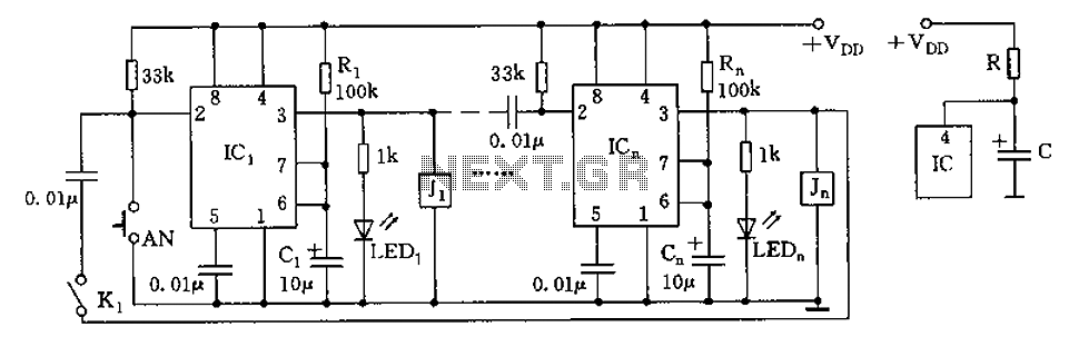
The frequency is Q1 and Q2, which will continue to use push pool work interchangeably. If this is the positive output signal Q1 Q2 will run the delete function this reason, C2 and C3 capacitors are half-wave alternating. Living in the current rush to waste time to even have little value. Electronic circuits, so one is important in everyday life. Which saves time and convenience. There is no output from the 3 pin. It make the current flows through R2, LED2 into three legs of IC1. The light LED2. But when a letter in the mail box to shield the light from the lamp. The LDR is not light. LDR will be much resistance. Voltage drop across the LDR is high enough to make IC1 work. Work of the circuit is IC1, R1, R2 and C1. The range of the A Stable Multi Vibrator, and the output is a square wave. It is a positive signal pulse frequency of 2. 3 kHz output pin 3 of IC1. And C3 and D1 connected to circuit CLAMP. That it serves to signal a positive pulse to pulse signal negative. The D2 and C3 act negative pulse signal is converted direct current (DCV) electrical signals. The negative power. Thus the output voltage to a negative DC electrical This is the circuit diagram of a ding dong sound generator based on two NE555 timer ICs.
The circuit is designed to toggle between two adjustable frequencies to produce the ding dong sound. The first NE555 (IC1) is wires as an astable multivibrator operating at 1Hz. The frequency of the second NE555 (IC2) is modulated by the output from the first IC. This is attained by connecting the output of first IC to the control pin (pin5) of the second IC. The tone of the sound depends on the frequency of the second IC and the changeover time depends on the freq 🔗 External reference
Related Circuits
The Door Buzzer circuit utilizes an IC 555 to generate a sound resembling an electric bell. When the switch S1 is pressed, a loud sound is produced. This circuit is designed to be simple and requires minimal components. It...
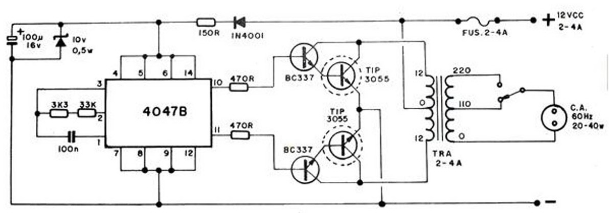
The converter transforms 12 VDC to 220 VAC, allowing for the conversion of 12 volts DC into 220 volts AC. The circuit diagram provided illustrates a simple converter circuit. This DC to AC converter can supply voltage for a...
This metal detector electronic project schematic circuit is designed using a simple 555 timer integrated circuit. The schematic circuit requires few external electronic components. The metal detector circuit utilizes the 555 timer IC in an astable mode configuration, which generates...

The following circuit is a power amplifier circuit for an FM transmitter with an output power of 30 watts. The power amplifier circuit utilizes a power transistor of type 2SC1946A. The FM transmitter operates with a 13.8-volt DC power...
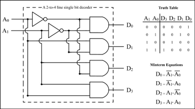
The Encoder and Decoder are different types of combinational circuits used to convert binary information to decimal, octal, and hexadecimal formats, and vice versa. A decoder is a combinational circuit that converts n-bit binary information into 2^n unique outputs....
The circuit depicted in the figure is designed for multi-temperature testing, allowing for the switching of the thermocouple corresponding to the active channel. At the core of this design is a 555 timer configured in a monostable delay mode....
Warning: include(partials/cookie-banner.php): Failed to open stream: Permission denied in /var/www/html/nextgr/view-circuit.php on line 713
Warning: include(): Failed opening 'partials/cookie-banner.php' for inclusion (include_path='.:/usr/share/php') in /var/www/html/nextgr/view-circuit.php on line 713