
555 timer Electronic roulette wheel circuit and explanation

The circuit design comprises several key components that work in unison to create the desired electronic roulette effect. The 4017 IC, a decade counter, has ten outputs that can drive individual LEDs. Each output corresponds to a different score on the roulette board. The 555 timer, configured as an astable multivibrator, produces a continuous square wave signal that acts as a clock input for the 4017 IC. The frequency of this clock signal is determined by the resistor and capacitor values associated with the 555 timer.
The S1 switch acts as a trigger to start the game. When pressed, it allows current to flow, charging capacitor C3 and initiating the clock signal. The variable resistor VR1 provides an adjustable resistance, enabling the user to change the frequency of the clock signal and thus the speed at which the LEDs cycle through the outputs of the 4017 IC. This feature adds an element of variability to the game, enhancing user experience.
As the game progresses, releasing the S1 switch cuts off the power supply to the circuit. The discharge of capacitor C3 causes the frequency of the clock signal to decrease gradually. This reduction in frequency results in a slowing down of the LED rotation, simulating the effect of a slowing roulette wheel. Eventually, the outputs of the 4017 IC cease to activate any LEDs, marking the conclusion of the game and allowing the player to view the randomly selected score.
To summarize, this electronic roulette game circuit effectively combines the functionalities of the 4017 decade counter and the 555 timer in astable mode to create an engaging and dynamic gaming experience. The design is relatively simple, yet it provides a clear demonstration of fundamental electronic principles, making it an excellent project for both educational and recreational purposes.This electronic circuit is a simple version of an electronic roulette game and is based on the 4017 IC which is a 10 stage decade counter/divider. It is driven by another versatile IC 555 configured as a voltage controlled oscillator (VCO). The 555 timer is connected as an astable multivibrator. When the S1 switch is pressed, the capacitor C3 get s charged, also at this point of time a constant stable clock is fed to the 4017 IC and the LEDs at its outputs light up in a cyclic manner producing a revolving effect. Adjusting the VR1 (variable resistor ) the speed of revolving effect can be varied. When the S1 switch is released, the main supply is cut-OFF, C3 discharges and forces the freely running astable to gradually stretch and slow down the time period of its output pulses so that eventually the oscillations stop within a stipulated time.
In response to these dying pulses the rotation of the LEDs connected to the output of IC 4017 also slow down gradually and stops to select a random score marked on the board. 🔗 External reference
Related Circuits
S1 and S2 are normally open, push-to-close, momentary switches. The diodes, which can be either red or green, serve solely to indicate the direction of operation. The TIP31 transistors may need to be adjusted based on the specifications of...
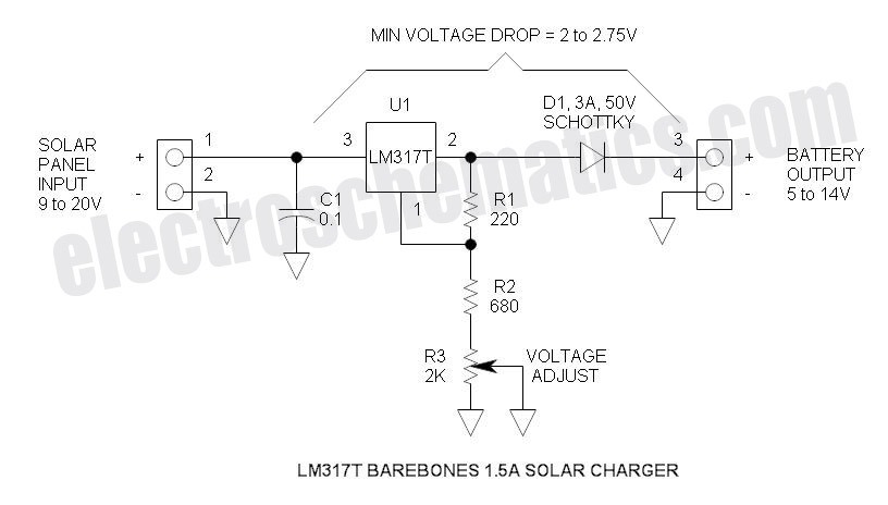
This solar battery charger is a simple and cost-effective project suitable for hobbyists. While it has some limitations compared to other similar devices, it offers several advantages. The charger is designed for lead-acid batteries but can also charge any...
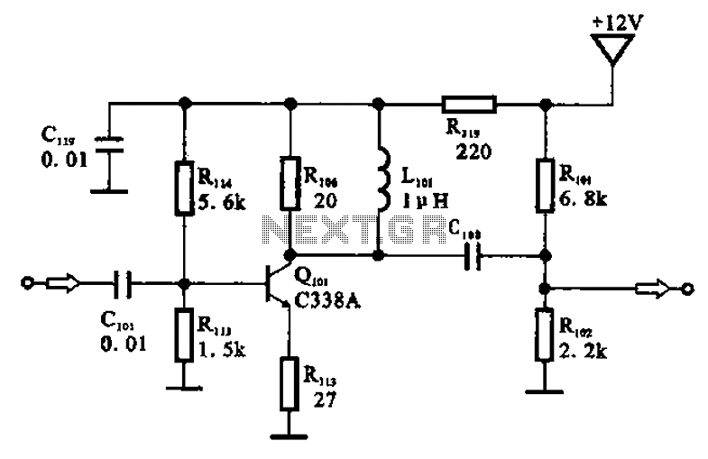
The amplifier circuit is designed as a pre-amplifier configuration. It utilizes transistor Q101 and other components such as inductor L101 and biasing elements. The transistor operates as a common emitter intermediate frequency (IF) amplifier. The IF signal is coupled...
Low-cost water pump controller circuit. The sensors used in the circuit can be any two conductive probes, preferably resistant to electrolytic corrosion. For example, a suitably sealed audio jack can be employed as the sensor. The automatic pump controller...
The circuit was quickly assembled from components available in a home lab and performed well during initial tests using a telephone line simulator and a line connected to a PBX. Reports indicate that this circuit functions effectively in Australia....

This is a simple yet effective charger for lead-acid batteries. It utilizes a 12-volt car bulb as both a current regulator and a charge status indicator. The described circuit is an innovative approach to charging lead-acid batteries. It employs...