
Electronic bio-wave therapy device
The electronic bio wave therapy instrument circuit operates on the principle of applying electrical signals to the body to stimulate healing and improve drug absorption. The circuit typically includes several key components: a microcontroller or signal generator, which produces the desired frequency signals; an amplifier to boost these signals; and electrodes that interface with the patient's skin.
The microcontroller is programmed to generate a range of frequencies, which can be adjusted based on the specific treatment protocol. These frequencies may vary widely, allowing for customization depending on the patient's condition and the intended therapeutic effect. The amplifier ensures that the signals are strong enough to penetrate the skin and reach the underlying tissues effectively.
Electrodes are strategically placed on the body to target specific acupoints or areas of pain. The design of these electrodes may vary, with some being adhesive pads and others being more specialized for particular applications. The placement and type of electrodes used can significantly influence the treatment's effectiveness.
Safety features are also an essential aspect of the circuit design. Overcurrent protection, isolation mechanisms, and user interface controls are implemented to ensure that the device operates within safe parameters. Additionally, the circuit may include a feedback system to monitor the response of the patient, adjusting the frequency or intensity of the signals in real time for optimal therapeutic outcomes.
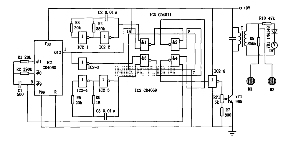
Overall, the electronic bio wave therapy instrument circuit represents a sophisticated approach to non-invasive treatment modalities, leveraging the principles of bioelectromagnetics to enhance patient care.Electronic bio wave therapy instrument circuit as shown, it can produce a variety of complex frequency electrical signals, the absorption of the drug can help patients affected area can also be a direct effect of treatment on the body points.
Related Circuits
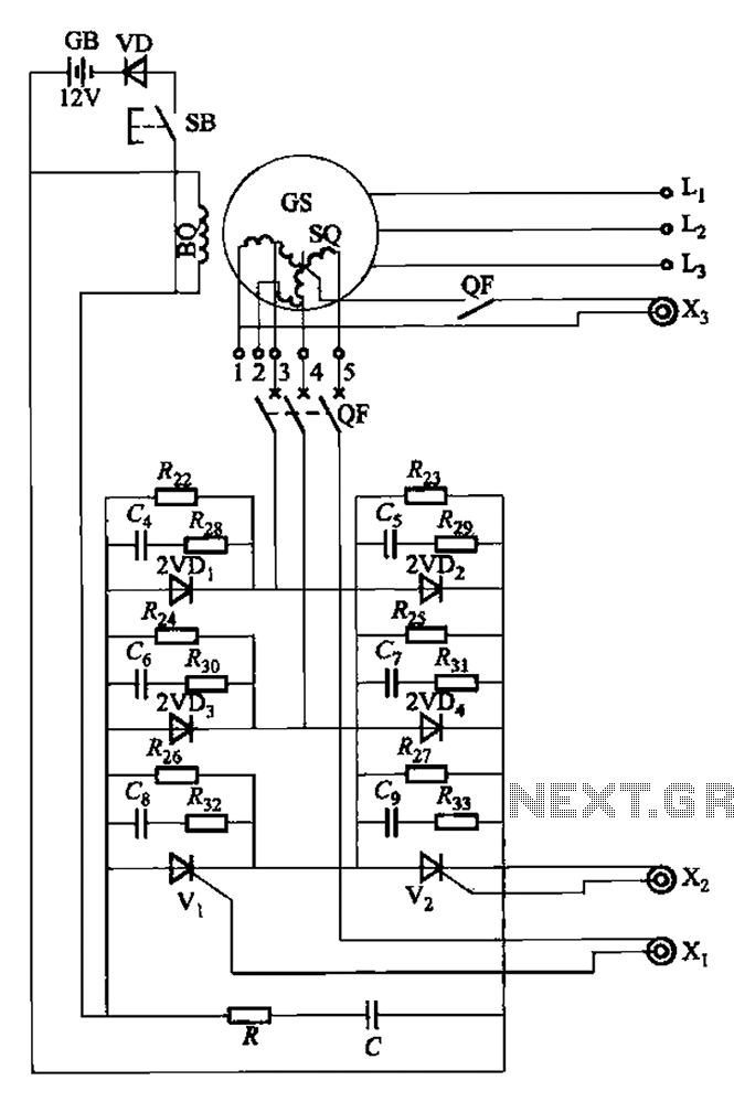
The setup is connected to separate stator windings of a harmonic generator, which leads to a thyristor rectifier supply for the third harmonic voltage, positioned after the motor field. The output voltage varies with changes in the winding harmonics...
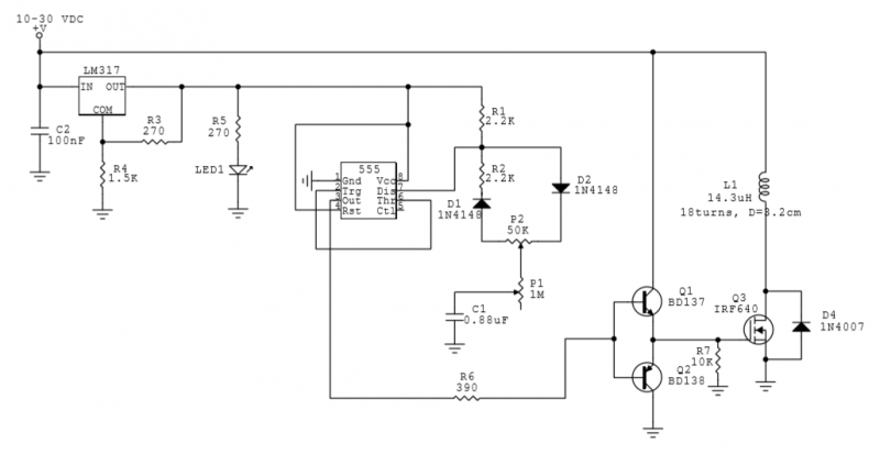
This circuit utilizes a 555 Integrated Circuit (IC) to generate a pulsed magnetic field, which can be employed for pulsed electromagnetic field (PEMF) therapy. The human body is affected by natural magnetic fields, including the Earth's magnetic field, geomagnetic...
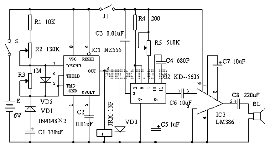
Cats are natural predators of rats, and the use of electronic devices to simulate meowing sounds as a repellent is an effective method. These electronic devices can produce meowing sounds at various frequencies and intervals, making them suitable for...
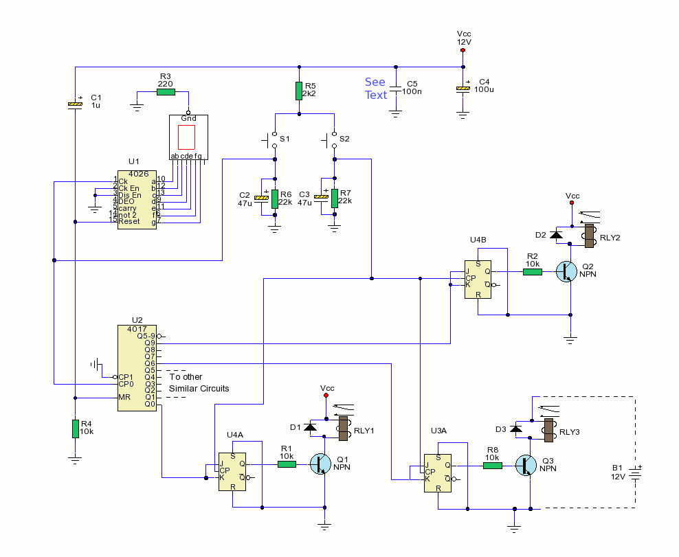
The schematic depicts two switches, S1 and S2, utilized for controlling the outputs. The primary function is executed by U2, a CMOS4017 decade counter divider integrated circuit (IC). Upon activation, capacitor C1 is swiftly charged through resistor R4, generating...
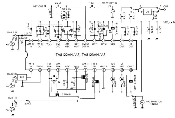
A simple low-power AM/FM radio receiver electronic project can be designed using the TA8122 integrated AM/FM receiver, manufactured by Toshiba Semiconductor. This radio receiver circuit is suitable for portable radio applications and similar devices. The TA8122 radio receiver circuit...

The input capacitor is used for low-frequency cut-off, with a standard value of 0.1 µF, resulting in a cut-off frequency of approximately 16 Hz. The input capacitor plays a critical role in electronic circuits, particularly in signal processing and audio...