
Electronic Buzzer with IC timer NE555
The circuit design incorporates the NE555 timer, which is widely recognized for its versatility in generating precise timing and frequency signals. In this configuration, it operates in astable mode, where it continuously oscillates between high and low states, thereby generating a square wave output.
The frequency of oscillation can be controlled by adjusting the resistor and capacitor values connected to the NE555 timer. Typically, two resistors (R1 and R2) and a capacitor (C1) are connected to the timing pins of the IC. The relationship between these components determines the frequency of the output signal, which can be calculated using the formula:
\[ f = \frac{1.44}{(R1 + 2R2) \times C1} \]
Where:
- \( f \) is the frequency in hertz (Hz),
- \( R1 \) and \( R2 \) are the resistances in ohms (Ω),
- \( C1 \) is the capacitance in farads (F).
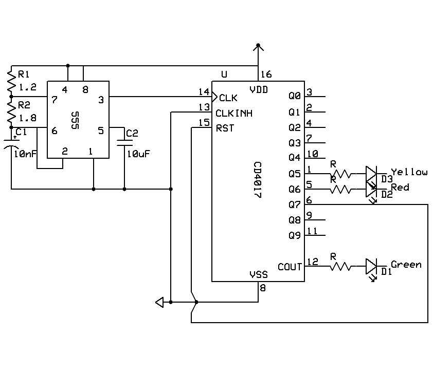
When the circuit is powered, the NE555 timer generates a square wave signal at the output pin (Pin 3), which can be connected to a piezo buzzer. The buzzer converts the electrical signal into audible sound. By adjusting R1, R2, or C1, the pitch of the sound can be modified to meet specific requirements.
Power supply requirements for this circuit typically range from 5V to 15V, making it suitable for various battery-operated devices. The simplicity of the design allows for easy implementation in hobby projects, educational demonstrations, or as a sound alert in various applications. Proper layout and component selection are essential to ensure the circuit operates efficiently and produces the desired sound output.This easy electronic buzzer circuit built based on timer works for gaining the frequency. The IC timer NE 555 used as astable multivibrator operating at about 1kHz and produces a sound when switched on. The sound frequency can be adjusted b.. 🔗 External reference
Related Circuits
The digital lock shown below uses 4 common logic ICs to allow controlling a relay by entering a 4 digit number on a keypad. The first 4 outputs from the CD4017 decade counter (pins 3,2,4,7) are gated together with...
A timer is being developed for circuit training or boxing training. The timer does not require any external input, except for a reset function. The project can be simplified using a microcontroller, such as the PIC12F635, which is cost-effective...
An electronic decorative peacock consists of 10 light-emitting diodes (LEDs), each of which contains multiple LEDs arranged in the tail of the peacock model. The light emission drive circuit operates the fan-shaped LEDs in a cyclic manner, emitting light...
When the current through the load exceeds a level determined by the position of the wiper on the 1k wire-wound pot, this circuit cuts off the load immediately. If S1 is open, the range is approximately 300-650 mA, and...

Here is a simple thermostat circuit that can be used to control a relay and supply power to a small space heater through the relay contacts. The relay contacts should be rated above the current requirements for the heater....
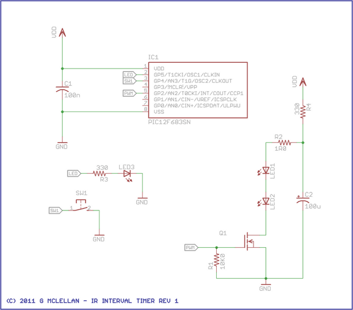
This project aims to build an infrared (IR) interval timer that can be utilized to capture images, such as time-lapse movies of sunrises and night skies. The IR interval timer circuit is designed to automate the process of taking...