
IR Interval Timer for Pentax DSLR Camera
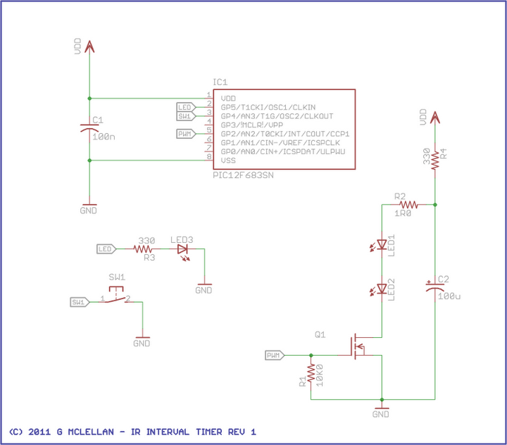
The IR interval timer circuit is designed to automate the process of taking photographs at specified intervals, making it ideal for capturing gradual changes in the environment, such as the transition from day to night. The core components of this circuit typically include a microcontroller, an infrared emitter and receiver, a relay or transistor for controlling the camera shutter, and a power supply.
The microcontroller serves as the brain of the timer, programmed to execute a series of commands that dictate the timing of the image capture. It can be programmed with various intervals, allowing the user to select how frequently the images are taken. The infrared emitter sends a signal to the receiver, which detects the presence of an object or person in front of the camera, ensuring that the timer only activates when needed.
A relay or transistor is used to interface with the camera's shutter mechanism. This component allows the circuit to control the shutter without requiring a direct connection to the camera, preserving the integrity of the camera's electronics. The power supply must be robust enough to support the entire circuit, ensuring stable operation during extended shooting sessions.
Additional features may include an LCD display for user feedback, allowing for easy adjustments to the timer settings, and buttons for user input. The design can also incorporate a battery backup system to ensure functionality in outdoor environments where power sources are not readily available.
Overall, the IR interval timer project combines various electronic components to create a versatile tool for photographers and videographers, enabling the capture of stunning time-lapse sequences with minimal manual intervention.This project aims to build an IR interval timer which can be used to capture images such as time lapse movies of sunrise or sunrise and the night sky. The.. 🔗 External reference
Related Circuits
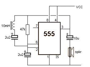
This metal detector electronic project schematic circuit is designed using a simple 555 timer integrated circuit. The schematic circuit requires few external electronic components. The metal detector circuit utilizes the 555 timer IC in an astable mode configuration, which generates...
This circuit illustrates the NE555 timer used in a light-sensitive alarm sensor circuit diagram. Features include the ability to detect a sudden shadow falling on the sensor. The NE555 timer is a versatile integrated circuit widely utilized in various timing,...
The 555 timer is commonly used in time-based circuit designs, particularly in monostable configurations. This setup is straightforward and requires only a few resistors and capacitors to achieve triggering. However, external interference can affect the operation of the circuit...
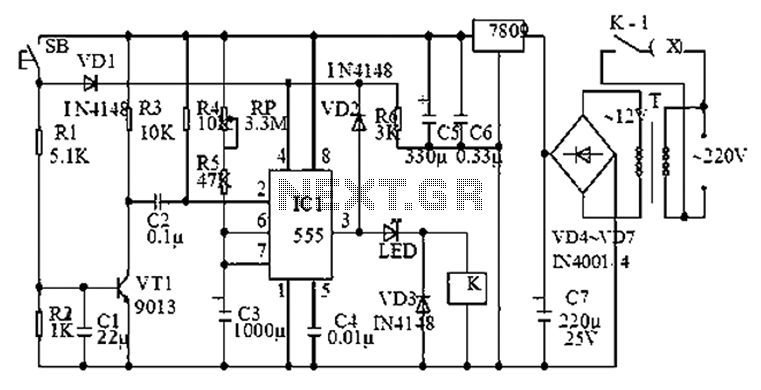
A wide range auto turn OFF timer covering 1 minute to 20 hours in three ranges with S1. As soon as power is applied to the circuit, the IC1 [555] starts to oscillate and feeds clock pulses to the...
The Proximity Camera Head (A2047) is a Long-Wire Data Acquisition (LWDAQ) device that interfaces with a TC255P image sensor. It is a radiation-tolerant evolution of the Inplane Sensor Head (A2036). The A2036 and A2033 are frequently used with the...
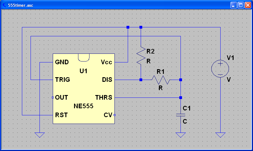
ECEN 2250 myDAQ Experiment Capacitors and the 555 Timer. The experiment involving capacitors and the 555 timer within the ECEN 2250 myDAQ framework focuses on understanding the behavior of capacitors in electronic circuits and the functionality of the 555 timer...
Warning: include(partials/cookie-banner.php): Failed to open stream: Permission denied in /var/www/html/nextgr/view-circuit.php on line 713
Warning: include(): Failed opening 'partials/cookie-banner.php' for inclusion (include_path='.:/usr/share/php') in /var/www/html/nextgr/view-circuit.php on line 713