
Electronic Canary

This modified Hartley oscillator circuit utilizes a small audio transformer (LT700) as its core component, facilitating the generation of oscillations at audio frequencies. The center-tapped primary winding, with an impedance of 1 kΩ at 1 kHz, allows for balanced operation, while the secondary winding's 8-ohm impedance makes it suitable for driving low-impedance loads, such as speakers.
The inclusion of resistor R1 and capacitor C1 is pivotal in creating the distinctive chirp effect. The 100 µF capacitor serves as an energy storage element, and its charging dynamics through the 4.7 kΩ resistor influence the timing of the oscillation. When the capacitor charges, it biases the transistor, allowing it to conduct and generate oscillations. Once fully charged, the bias is cut off, halting oscillation. The discharge of the capacitor through the transistor's base-emitter junction restarts the oscillation cycle, creating a repetitive chirp sound.
Variations in component values, such as changing the resistance of R1 or the capacitance of C1, directly affect the frequency and duration of the chirp, enabling fine-tuning of the circuit's acoustic properties. Additionally, the chirp's frequency is voltage-dependent, meaning that changes in supply voltage will also influence the behavior of the oscillator.
The operation of the circuit is further controlled by a push-button switch, which facilitates the charging of the 100 µF capacitor. When the switch is pressed, the capacitor accumulates charge, and upon release, the rapid discharge through the transistor leads to a quick succession of oscillations, resulting in a faster chirp. This interaction between the capacitor, resistor, and the transistor forms the heart of the oscillator's functionality, making it a versatile circuit for generating audio signals with unique characteristics.This circuit is a modified hartley oscillator with a couple of extra components included. The transformer is a small audio transformer, type LT700. The primary is center tapped with an impedance of 1Kohms at 1KHz. The secondary has an impedance of 8 ohms. The inclusion of R1 and C1 give this oscillator its characteristic "chirp". As the 100u capa citor charges via the 4. 7K resistor, R1 the bias for the transistor is cut off. This causes the oscillation to stop, the capacitor discharges through the base emitter circuit of the transistor and oscillations start again. Altering these components alters the frequency of the chirp. The chirp is also voltage dependent. When the push button switch is operated the 100u capacitor is charged. When its released, the oscillation decays and the chirp becomes faster. 🔗 External reference
Related Circuits
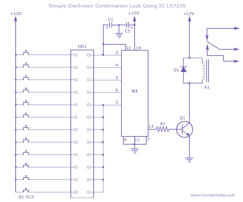
This circuit diagram illustrates a simple electronic combination lock utilizing the IC LS7220. It is designed to activate a relay for controlling any device (on & off) when a specific combination of four digits is entered. The circuit operates...

Electronic FM Telephone Transmitter Schematic. The following schematic design illustrates a circuit diagram for an FM telephone transmitter built on a compact PC board layout. This small design allows it to be easily integrated within the housing of a...
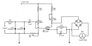
The electronic tachometer frequency converter circuit operates by converting the input signal into a proportional current that can be measured by a pointer device. The electronic tachometer frequency converter circuit is designed to accurately measure the rotational speed of a...
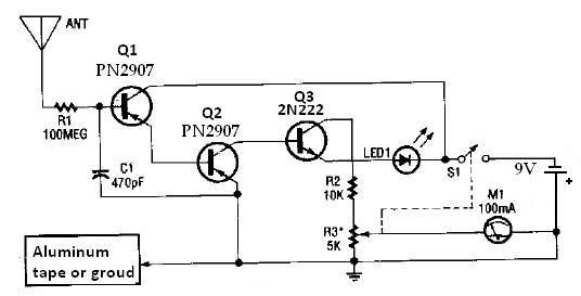
This ion detector circuit is designed to sense static charges and free ions present in the air. It is capable of detecting the presence of free ions, static electricity, or high voltage leakage. The project utilizes a short whip...
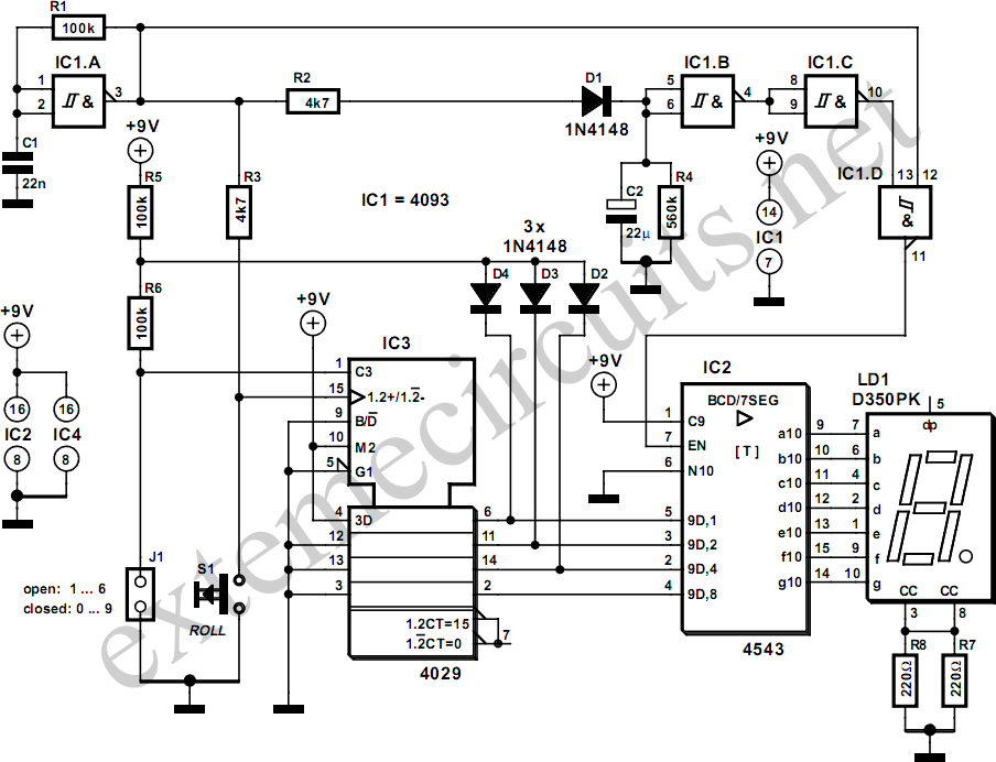
The simplicity of a traditional die makes it exceptionally difficult to create a fully equivalent electronic version, primarily because an electronic version necessitates a power supply and a collection of electronic components that occupy a significantly larger volume than...
The electronic multimeter is a versatile general-purpose instrument capable of measuring both DC and AC voltages, as well as current and resistance. This solid-state device typically includes a built-in power supply for operation on AC mains and often features...