
Electronic Multimeters
The electronic multimeter functions as an essential tool in various applications, including electrical diagnostics and circuit testing. The balanced-bridge configuration enhances measurement accuracy by minimizing the effects of component mismatches and thermal drift. The use of field effect transistors (FETs) in the design allows for high input impedance, making the multimeter suitable for measuring sensitive circuits without affecting their operation.
In practical terms, the PMMC (Permanent Magnet Moving Coil) meter provides a clear and direct reading of voltage and current levels, while the resistance measurement feature allows users to assess the integrity of components within a circuit. The implementation of a range switch and voltage divider enables users to select appropriate measurement ranges, accommodating a wide variety of electrical conditions. This flexibility is vital for technicians and engineers who require precise measurements in their work.
To ensure optimal performance, regular calibration of the multimeter is recommended. This process involves comparing the multimeter's readings against known standards and making adjustments as necessary. Additionally, proper care and maintenance of the device, including battery checks and cleaning of contacts, will prolong its lifespan and accuracy.
Overall, the electronic multimeter represents a significant advancement in measurement technology, combining versatility with precision in a compact and user-friendly design. Its ability to accurately measure voltage, current, and resistance makes it an indispensable tool for professionals in the field of electronics and electrical engineering.It is one of the most versatile general purpose instruments capable of measuring dc and ac voltages as well as current and resistances. The solid-state electronic multimeter (or VOM) generally consists of the following elements. In addition, the instrument is usually provided with a built-in power supply for operation on ac mains and, in most case
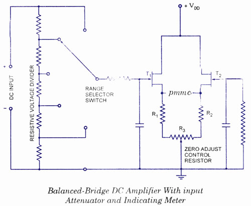
s, one or more batteries for operation as a portable test instrument. The schematic diagram of a balanced-bridge dc amplifier using two field effect transistors (FETs) is given in figure. It is to be noted that two FETs used in circuit should be reasonably well matched for current gain to ensure circuit thermal stability.
The two FETs and the source resistors Rx and R2, together with zero adjust control resistor R3, constitute a bridge circuit. The PMMC meter is connected between the source terminals of the FETs, representing two opposite corners of the bridge.
In the absence of input signal, the gate terminals of the FETs are at ground potential and the transistors operate under identical quiescent conditions. Ideally no current should flow through the PMMC movement but in practice, on account of some mismatch between the two FETs and slight tolerance differences in the values of various resistors a current doesflow and causes the meter movement to deflect from zero position.
This current is reduced zero by the adjust control resistor R3. Now the bridge is balanced. With a positive input signal applied to the gate of input transistor T1 its drain current creases causing the voltage at the source terminal to rise. The resulting unbalance between the two transistors T1 and T2 source voltages is shown by the meter movement, whose scale is calibrated in terms of the magnitude of the applied input voltage.
The maximum voltage that can be applied to the gate of input transistor T1 is deter mined by its operating range, which is usually of the order of a few volts. The range of the bridge can easily be extended by employing an input attenuator or a range switch, as illustrated in figure.
The unknown dc input voltage is applied through a large resistor in the probe body to a resistive voltage divider. Thus, with the range switch in the 3-V position as illustrated, the voltage at the gate of the input transistor T1 is developed across 8 MQ resistor of the total resistance of 11.
3 MQ and the circuit is so arranged that the PMMC meter gives full scale deflection with 3 V applied to the tip of the probe. With the range switch in 1, 200 V position, the gate voltage is developed across 20 kilo ohm of the total divider resistance of 11.
3 Mega ohms and an input voltage of 1, 200 V will he required to cause the full-scale meter deflection. When the multimeter`s func tion switch is placed in the OHM position, the unknown resistor is connected in series with an internal battery, and the PMMC meter simply measure the voltage drop across it (unknown resistor, Rx).
A typical circuit is given in figure. In the given circuit, a separate divider network, employed only for the meas urement of resist ance, provides a number of different resistance ranges. With the unknown resistor Rx con nected to the OHM terminals of the multimeter, the battery supplies current through one of the range resistors and the unknown resistor to ground.
Voltage drop across unknown resistor Rx, Vx is applied to the input of the bridge amplifier and the PMMC movement deflects. Since the voltage drop across Rx is directly proportional to its resistance, the meter scale can be calibrated in terms of Kilo ohm.
The worth noting point is that this instrument indicates increasing resistance from left to right whereas the conventional meter, indicates increasing resistance from right to left. This is because the electronic multimeter reads a large resistance as a higher voltage, whereas the conventional multimeter indicates a higher resistance as a smaller current.
🔗 External reference
Related Circuits
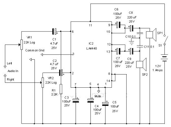
The LA4440 audio amplifier IC can be utilized to design a straightforward stereo power audio amplifier project, capable of delivering 6 watts of output power into an 8-ohm load. This audio amplifier IC features a minimal number of external...
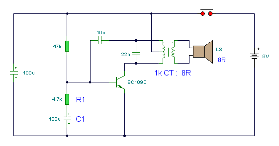
An electronic version of a chirping canary. It may be used as an alarm, a sound effects generator, or perhaps a replacement doorbell. The electronic chirping canary functions as an auditory signaling device, capable of generating a variety of chirping...
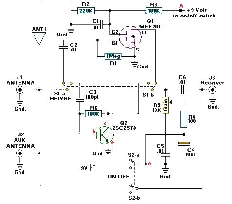
A simple and efficient active antenna electronic project can be designed using this electronic schematic circuit based on transistors. This active antenna project is effective for a wide range of RF frequencies, covering three RF bands: HF, VHF, and...
Modern ICON electronic engine controls from BRP The ICON electronic engine control system developed by Bombardier Recreational Products (BRP) represents a significant advancement in marine technology. This system integrates sophisticated electronic controls to enhance the performance and reliability of marine...
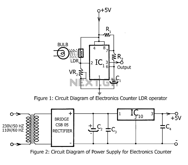
Simple counting can be performed by anyone, but counting over large intervals can be tedious and prone to errors. A previously published project, the Digital Counter, serves as a foundation for this electronics counter, which is the second project...
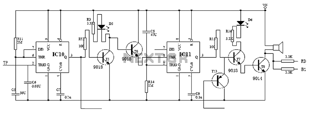
Child lock voltage comparator 555 monostable circuit, a counter, JK flip-flop, UPS power supply design digital logic circuit, electronic door control, and various additional circuitry to ensure the safety circuit can operate with a high safety factor. The circuit...