
Spy RF Bug Detector Circuit

The RF bug detector circuit functions by utilizing radio frequency signals to identify hidden transmitting devices. The key components of the circuit include an RF amplifier, a frequency mixer, a signal detector, and an audio output stage.
The RF amplifier is responsible for boosting weak signals received from the environment, ensuring that even low-power transmissions can be detected. The frequency mixer combines the incoming RF signals with a local oscillator signal to produce an intermediate frequency (IF) signal. This IF signal is then processed by the signal detector, which can be a diode or a dedicated RF detector IC. The detector extracts the audio or modulation information from the IF signal, allowing the user to discern the presence of a transmitting device.
The audio output stage typically consists of an audio amplifier that converts the detected signals into audible sounds, alerting the user to the presence of a bug. Additionally, a simple LED indicator may be incorporated to provide a visual cue when a signal is detected.
Power supply considerations are essential for this circuit, as it may require a regulated voltage source, typically ranging from 5V to 12V, depending on the components used. Battery operation is also a viable option for portability, making the device suitable for field use.
In summary, the RF bug detector circuit is a straightforward yet effective tool for identifying hidden surveillance devices, employing a combination of RF amplification, signal mixing, detection, and audio output to provide feedback to the user. Proper selection of components and careful design will ensure optimal performance across the specified frequency range.Here is a simple RF bug detector that will help you detect spy bugs and can operate up to 2 GHz. Below are some essential things required for this circuit:.. 🔗 External reference
Related Circuits
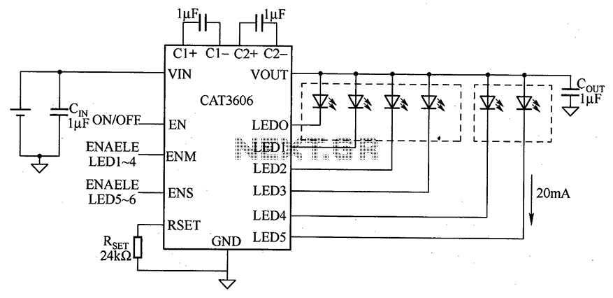
CAT3606 is a high-efficiency white LED driver. This adjustable charge pump is suitable for general-purpose, large-panel, flicker-free white LED backlighting and dual-display systems. The CAT3606 inductor boost circuit can replace conventional high-brightness backlighting requirements, thereby simplifying system design. It...
Using a wire connection, utilize the NFA.55 timebase circuit delay type light touch switch, which can directly replace an ordinary mechanical switch without needing to modify the original internal wiring. The circuit is powered back with good hoof Chapter...

This two-zone alarm features automatic exit, entry, and siren cut-off timers. It was designed for the Beginner's Guide to CMOS Timers, providing a particularly detailed circuit description. An optional One-Time-Only module is available, which will deactivate the siren after...

There was difficulty in understanding that the Source pin connects to low voltage (source of electrons) and the Drain pin connects to high voltage (absorbs electrons). This concept is fundamental to basic electricity, but it required some time to...

Two gates of a 4011 IC are utilized as a comparator. When the resistance of R4 decreases, the voltage at pins 1 and 2 increases, resulting in a logic zero at pin 3. This causes pin 4 to go...

The circuit utilizes a dual sound multi-frequency encoding signal to modulate the emitted carrier frequency, forming a DTMF encoding wireless calling system. It incorporates the DTMF encoding circuit UM97085 and the decoding circuit YN9101 to create a micro wireless...