
temperature controller using ds1820 and lcd display
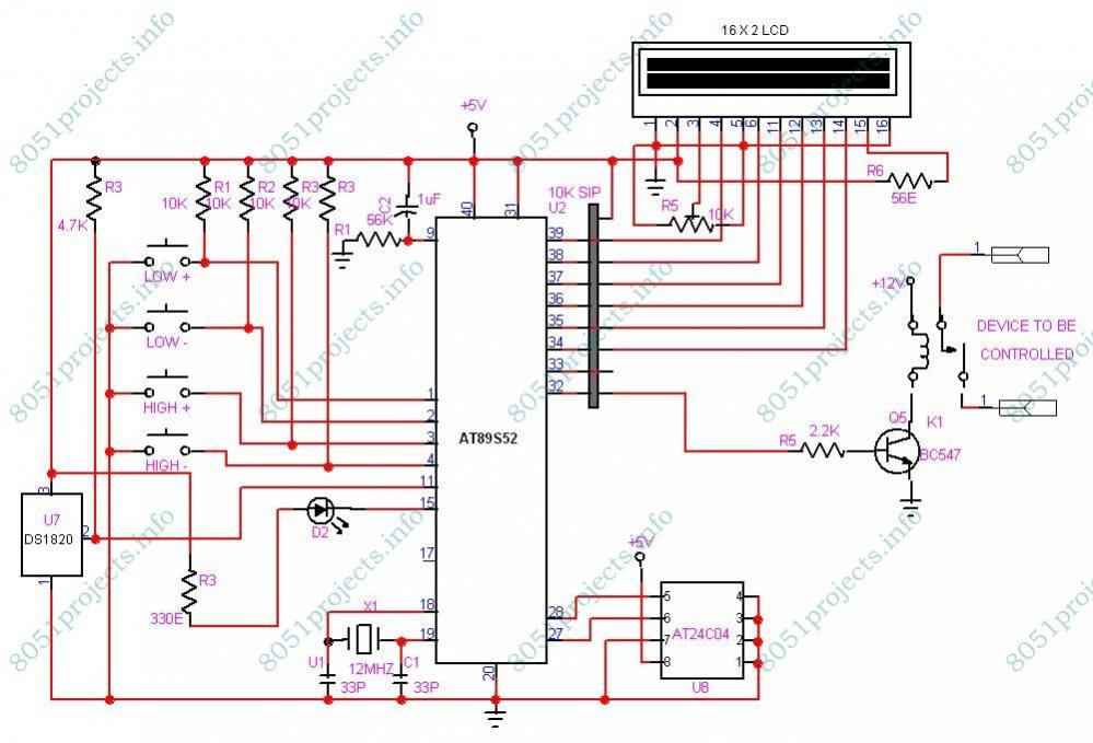
The temperature monitoring and control system is structured around a central microcontroller, the AT89S52, which orchestrates the entire operation. The DS1820 sensor, known for its accuracy and ease of integration, measures the ambient temperature and transmits this data to the microcontroller using a 1-wire communication protocol. This minimizes the number of required connections, simplifying the circuit design.
The LCD display serves as the user interface, providing real-time temperature readings and allowing users to set desired temperature thresholds. The system includes four tactile switches for user interaction. Two switches are dedicated to adjusting the high temperature limit, while the other two adjust the low limit. This allows for flexible configuration based on user requirements.
To ensure that the preset temperature limits are retained even when the system is powered down, an external EEPROM (24C02) is utilized. The AT89S52 communicates with this EEPROM via the I2C protocol, enabling it to read and write the temperature limit values as needed. This setup is essential for preserving user settings and providing consistent operation across power cycles.
When the temperature exceeds the defined high limit, the microcontroller activates a relay, which can control an external device, such as a cooling fan or heater, to bring the temperature back within the desired range. The system continuously monitors the temperature and adjusts the relay state accordingly, ensuring that it operates within the user-defined parameters.
In summary, this temperature monitoring and control system exemplifies a practical application of microcontroller technology, integrating various components and communication protocols to achieve reliable and user-friendly operation. The careful selection of components, such as the DS1820 sensor and 24C02 EEPROM, enhances the system's functionality and performance, making it suitable for a variety of temperature control applications.This Project is used to indicate the temperature and it is also used as controller. The system will get the temperature from the DS1820 and it will display the temperature over the LCD display. There are 2 preset levels, one is low preset and the other is High preset. The temperature was compared with the value stored by the user and if the temper ature goes beyond the High Preset temperature then an relay is switched ON until the temperature comes below the Low preset temperature. The System is fully controlled by the microcontroller AT89S52. It is a popular 8 bit microcontroller. The circuit consists of four switches, in which two buttons are used to increment and decrement the High limit temperature value and the other two buttons are used to increment and decrement the Low limit temperature value.
The temperature limits are stored inside the EEPROM, since 89s52 dont have inbuilt eeprom. The IC 24C02 is the eeprom chip and it is connected to the microcontroller through the I2C bus. The DS1820 is the temperature sensor chip which is connected to the microcontroller through 1 wire bus. 🔗 External reference
Related Circuits
Integrated-circuit U1-an LF351 or 741 op amp-is used as a comparator to control the light. Resistors R2 and R3 provide a reference voltage of about 2.5 volts at pin 3 of U1. When daylight falls on light-dependent resistor LDR1,...
This integrated circuit is highly efficient and does not require any external glue logic for operation. It features two pins to control a motor: one for direction and the other for stepping pulse triggers. The design is compact and...
Many of today's appliances feature displays and buttons. Instead of relying on motors and gears, numerous household items now incorporate embedded microcontrollers. This exploration focuses on how to experiment with microcontrollers at home. Microcontrollers serve as the central processing units...
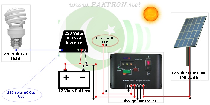
A solar charge controller is an electronic device used in solar system installations to regulate the amount of charge directed toward a battery from a solar panel. Charge controllers come in various types and ratings. The term "charge controller"...
This circuit illustrates the TDA1054 tone control stereo preamplifier circuit diagram. Features include the National Semiconductor LM35 integrated circuit, which utilizes semiconductor technology. The TDA1054 is a versatile integrated circuit designed for use in audio applications, particularly in tone control...
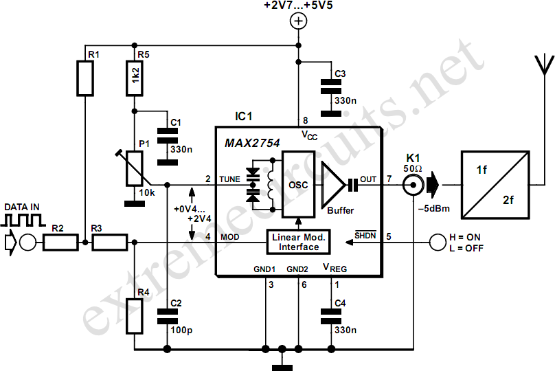
High-frequency voltage-controlled oscillators (VCOs) are challenging to construct, which is why Maxim has developed the integrated 1.2 GHz oscillator, the MAX2754. The center frequency is adjustable via the TUNE input, while a linear modulation input allows for frequency modulation....
Warning: include(partials/cookie-banner.php): Failed to open stream: Permission denied in /var/www/html/nextgr/view-circuit.php on line 713
Warning: include(): Failed opening 'partials/cookie-banner.php' for inclusion (include_path='.:/usr/share/php') in /var/www/html/nextgr/view-circuit.php on line 713