
MODULATED PT2399 CIRCUIT
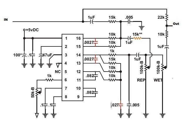
The PT2399 is a digital delay chip renowned for its simplicity and compactness, often used in DIY audio effects. In this circuit, the chip operates within its limitations, specifically regarding storage and noise output. The implementation of capacitors at the input stage is a critical design choice, effectively filtering high-frequency noise that could degrade audio quality. The stability of the Low-Frequency Oscillator (LFO) is paramount, as it directly influences the modulation effects applied to the delay time. The inclusion of an SPDT switch allows for versatile waveform selection, enhancing the functionality of the circuit in a live performance setting.
The audio tests reveal a range of delay effects, demonstrating the circuit's capability to produce various auditory experiences, from ambient sounds to rhythmic slap-back delays. The transition from a breadboard prototype to a finalized stompbox design will involve careful consideration of component placement, soldering techniques, and enclosure design to ensure durability and ease of use.
Further refinement of the gain settings in the mixing circuit, utilizing the TL082 op-amp, will be essential to achieve the desired output levels. The exploration of microcontroller integration, particularly with the ATMEGA328, suggests a future direction that could enhance the versatility of the circuit, allowing for programmable effects and more complex modulation techniques.
In summary, this project embodies a comprehensive approach to utilizing the PT2399 chip in creating a digital delay effect pedal, incorporating various modulation techniques, and addressing challenges related to noise and stability. The ongoing experimentation and documentation of the design process contribute to the broader DIY audio community, fostering innovation and collaboration among enthusiasts.i`ve been wrapped up in Jeep repair lately as there`s some sort of issue prevent the beloved XJ from firing up. i have, however, in the meantime had some time to work through my initial modulation tests on this version of the PT2399 circuit and nail down a lot of the bugs.
the initial problems were stabilizing the LFO and purging the noise from th e chip. as you well know from the datasheet, the PT2399 has very little storage space. it also makes a lot of racket on the output of pin 14. i was able to use 2nF caps on the input to really filter some of that out and get the thing pretty quiet. the LFO problems were locked down thanks to the EchoBase schematic. the final draft will an SPDT which will switch between the square and triangle wave. the audio test features only the triangle side of things. as for the audio, the first part is long delay with light modulation and moderate rate. the second is short delay with slow modulation, and the last is kind of a slap-back delay with faster modulation.
i`m really looking forward to getting this one off the breadboard and into a usable stompbox. thanks to all of those people at DIY Stomp boxes who post information. it`s been a big help. a breadboard version of some PT2399 modifications i`ve been working on. there are a lot of DIY schematics that utilize the PT2399 (Magnus Modulus, Echo Base delay, Rebote, etc. ). i`ve been interested at trying my hand at modulation techniques recently. i made a simple LFO circuit based on the findings mentioned in a previous post. i used some techniques out lined in some of the schematics floating out there to attempt to modulate the delay time of the chip.
i wouldn`t say i`ve got it to work perfectly, but it`s definitely doing what i had hoped. this is an older build now, but i wanted to post it while i`ve been on the subject to record the process. believe it or not, i still have some work to do on this one. i used a TL082 as a buffer for the mixing circuit. getting the gain set to my taste has been the toughest part. this one (unlike the last) is a bit low. it will all come in due time though. i`ve produced two solid builds this week (though really just debugging this one and one from scratch), and i`ll consider that a productive week.
well, not really. feeble attempt and making some sort of microprocessor controlled tempo clock, but a good exercise in the ATMEGA328s finicky behavior. don`t ask me what that squeal is. i think it comes from the way the input was wired up (mistaking the second sleeve as a synonym for ground) coupled with the PWM stream not having a negative offset, but who knows.
eventually, i`ll move off the tone() crutch and start working with more interesting DSP. it`ll be nice to start using some of the memory on the chip. i will also post the schematic for the delay pedal once i`ve got the values i want in it. i won`t have any time nor tools to tear into it until next week though. Essentially the oBITerator program with aerials instead of actual input signal. Of course, we`ve got to mix in the newly constructed PT2399 pedal. A little work needs to happen in the common-collector preamp which I`m mainly using to lower the input impedance into the delay chip. I`ll be recalculating those values soon as well as switching out a couple of the ceramic caps. They sounded good on the bread board initially, but I`d like to have a little less cutoff. Of course, no experiment would be complete without an LM386-based cigar box amplifier powering a Weber 12 ³ signature alnico.
i`ve been experimenting with this PT2399 chip and using various schematics to create a digital delay circuit. the delay time seems to be directly attached to the sample rate since lengthening the delay time gives a nice decrease in pitch.
i`m toying with the idea of dropping a time constant in around the controlling delay time circuit to see about achieving a tape warble sort of effect. we`ll see what works. Audio clip: Adobe Flash Player (version 9 or above) is required to play this audio clip. Download the latest version here. You also need to have JavaScript enabled in your browser. 🔗 External reference
Related Circuits
Figure 1-87 illustrates an effective loudness volume control circuit that employs a standard potentiometer. The components used are minimal, yet the performance is notably impressive. The operation principle is as follows: when the internal impedance of the source is...
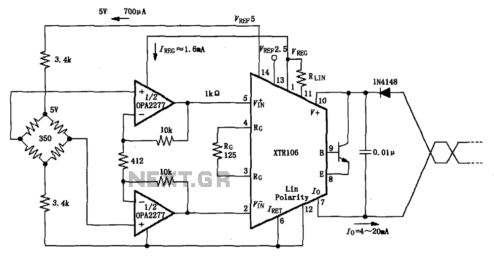
The XTR106, as illustrated in the figure, features two internal source voltages of 2.5V and 5V, enabling it to accommodate a wide range of bridge values without the need for additional circuitry. It can operate with bridge resistances lower...
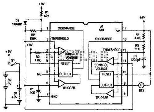
The two timers in the bug repeller exhibit notable characteristics. Both have their thresholds set externally; the oscillator on the left operates with a 50% duty cycle, while the oscillator on the right functions as a voltage-controlled oscillator (VCO). The...
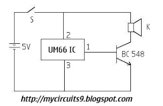
This is a circuit diagram for a simple doorbell. The circuit can be assembled indoors, while the switch should be placed outside, making it easily noticeable for visitors. The operation of this circuit is similar to a previous project. The...
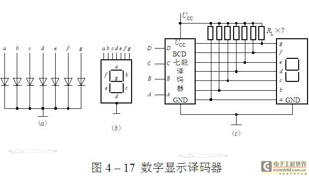
The luminescent diode (LED) is constructed from gallium arsenide (GaAs), a specialized semiconductor material, and gallium arsenide phosphide. It can be used individually or assembled into segment-type or lattice LED display devices. The display unit consists of a sectional...
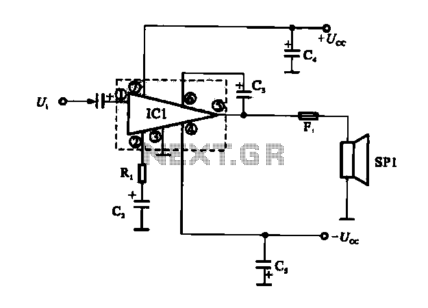
The OCL power amplifier circuit is an integrated circuit. Circuit IC1 is an integrated circuit, and its internal circuit configuration is substantially similar to the OTL power amplifier circuits. The OCL (Output Capacitor-Less) power amplifier circuit is designed to provide...