
electronic marx circuit and gas

The Marx generator is a type of electrical circuit used to generate high-voltage pulses. It consists of a series of capacitors and spark gaps arranged in a specific configuration to achieve rapid charging and discharging. The basic principle involves charging multiple capacitors in parallel and then discharging them in series, which results in a high-voltage output.
In a typical Marx generator setup, several capacitors are connected to a common voltage source. Each capacitor charges up to the source voltage. Once the capacitors are fully charged, the spark gaps are triggered, creating a conductive path between them. This allows the stored energy in the capacitors to discharge through the spark gaps in series, effectively adding the voltages of each capacitor together. The result is a much higher voltage pulse than what would be possible with a single capacitor alone.
The configuration of the Marx generator allows for precise control over the timing of the discharge, which is crucial for applications such as high-voltage testing, pulsed power applications, and electromagnetic pulse (EMP) generation. Additionally, the ability to scale the generator by adding more capacitors and spark gaps provides flexibility in designing circuits for specific high-voltage requirements.
The advantages of the Marx generator include its simplicity, efficiency in generating high-voltage pulses, and the ability to produce short-duration, high-energy outputs. It is commonly used in research laboratories, industrial applications, and as a component in various high-voltage experiments. Understanding the operational principles and configuration of the Marx generator is essential for engineers and researchers working in fields that require high-voltage technology.Writing about multiple circuits in Marx, I have just discovered (shame for not knowing this) an entire new set - indeed, billed as `the` Marx Generator. There are, of course, also diagrams, and a useful quote: `The main advantage of the Marx circuit configuration over a more direct approach to charging is that it overcomes..
🔗 External reference
Related Circuits
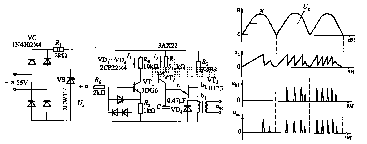
Due to the increased level of the transistor amplifier circuit, the control circuit's performance in Figure 16-6 is more sensitive and can accept input control signals superimposed on others (such as voltage, current, and speed feedback signals) to meet...
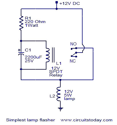
This is a simple lamp flasher circuit that utilizes only three components (a capacitor, a relay, and a resistor) in addition to the lamp. The operation of the circuit is straightforward. When power is turned on, the capacitor C1...
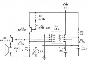
The following circuit illustrates a Sun Up Alarm Light Alarm Circuit Diagram. This circuit is based on the 555 Integrated Circuit (IC). Features include simplicity and cost-effectiveness. The Sun Up Alarm Light Alarm Circuit employs the 555 timer IC in...
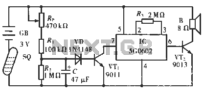
The circuit operates in such a way that when the patient is typically in an upright position, the SQ mercury switch is turned off, resulting in the alarm circuit being inactive. When the patient lies down, the SQ switch...
The following circuit illustrates a 2500W Phase Control Circuit Schematic. Features include a ground-tied trigger output that is disabled, and a low voltage input. The 2500W Phase Control Circuit is designed to regulate the power delivered to a load by...
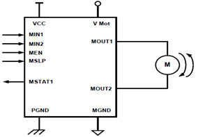
The schematic presented illustrates a 5A H-Bridge Module designed for the operation of a single Bipolar DC motor. The H-Bridge Module includes a header set (J2) and a connector terminal set (J1). Below is the pinout description for the...