
Electronic Thermometer Circuit

The described thermometer circuit is a compact and efficient design that leverages the characteristics of temperature-sensitive components to achieve reliable measurements. The use of LM34 or LM35 temperature sensors ensures that the circuit can operate without the need for calibration, making it user-friendly and accessible for hobbyists and educators alike. The careful balancing of temperature coefficients through the use of fixed current devices and adjustable resistors contributes to the circuit's stability and accuracy.
In practical applications, this circuit can be utilized in various temperature monitoring scenarios, from educational projects to more advanced temperature measurement systems. The design allows for easy integration with other electronic systems, thanks to the straightforward connections and minimal power requirements. The attention to thermal management and layout design ensures that the circuit remains stable under varying environmental conditions, making it suitable for both indoor and outdoor applications.
Additionally, the option to create a printed circuit board (PCB) from the provided PDF enhances the usability of the design, allowing for reproducibility and customization. The inclusion of a multimeter connection facilitates real-time monitoring of temperature readings, while the provision for an internal panel meter adds versatility to the design. Overall, this thermometer circuit represents a practical solution for accurate temperature measurement while being educational and engaging for electronics enthusiasts.There are plenty of digital thermometers with ·1 C displays but the accuracy is about + 1 C and you can not calibrate them. I made this thermometer circuit from components that were available at the local electronics hobby shop and it was an educational experience.
If you want a simple modern circuit that requires no calibrating I recommend you look at a circuit that uses the LM34 or LM35. In the circuit above T2 is a fixed current device that sinks approximately 70 Micro amps. P1 is adjusted so that this current does not vary with temperature by balancing the negative temperature coefficient of T1 with the positive coefficient of T2. R3 reduces the effect that adjusting P1 has on the set current. T4 provides a current proportional to the absolute temperature and is adjusted to equal the fixed current through T2 at 0 C.
Thus at any temperature other than 0C a current must flow into or out of the voltage divider formed by R7 and R6 and provide a voltage for the meter as it flows through P3 and R5. P3 is adjusted so that at some standard temperature the 200 milli Volt meter reads correctly. Simply put T4 is a Kelvin thermometer and T2 subtracts 273. 15 to convert it to a Centigrade one. The LM334z (T4 - T2) is a readily available device that provides a current source that is directly proportional to the absolute temperature ( K ) over the range 0 to 70 °C for larger ranges there are other devices in the same family that can be substituted.
Great care was taken to ensure that temperature changes to the body of the instrument do not cause changes to the readings. T2 has changes nulled by P1 but the resistors themselves change value with temperature and this is also canceled out as follows.
Any change to the resistance of R1, P2 and P1, R2, R4, R3 with the temperature of the instrument body will cause changes to the current of T4 and T2 but the same change will occur to P3 and R5 and keep the voltage across them constant. For example if all the resistors went up 10% there would be 10% less current through T4 and 10% less through T2 and the difference in the currents would be 10% less through P3 and R5 but as they would have 10% more resistance the output voltage would stay the same.
Any change in the output of T3 with temperature has no effect. The circuit was laid out paying attention to keeping T2 and T1 close together and the resistors that could cause temperature drift in close proximity. An Acrobat reader. pdf file of this is provided and can be printed full size and used to hand make a PCB using a etch resist pen or to photo etch a board if required The sensors T4 is connected by 3 wires.
Thin twin shielded wire was used with the shield connected to the + rail (V+). The connection to the multimeter was made with flying leads fitted with pin sockets insulated by heat-shrink. Left shows a bottom view of T4. Power consumption is a couple of milli-amps so it can be powered by a 9 Volt battery. A panel meter if used can be run from the 5 Volt supply but it must be a meter that can be run with a common power supply and floating inputs.
T1 and T2 should be in close thermal contact. Winding copper wire around them and applying heat-sink thermal grease will aid stability. The red wire with the knot just passes through the board as the switch is on the opposite side of the board to the battery connector. The 4 unused holes (top right) are are for the power leads to an optional internal panel meter. 🔗 External reference
Related Circuits

This is a design circuit for a UHF transmitter. The TV transmitter operates within the UHF frequency range of 470-580 MHz, specifically on channels 21-34. It can transmit signals over distances of 30-100 meters using a cable length of...

Right- and left-channel signals pass through buffer amplifiers C4-a and C4-b into the active crossover IG5. Low frequencies are directed to mixer IC6-c, while middle and high frequencies are sent to analog delay lines 1C1 and 1C2. The output...
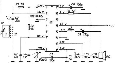
This AM radio receiver circuit utilizes the TDA1083 radio IC, which is suitable for constructing a simple medium frequency (MF) band radio. The schematic operates within a frequency range of 300 kHz to 3 MHz. The circuit is straightforward...
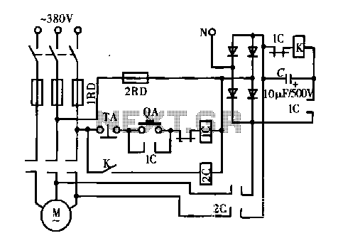
A DC motor is depicted in a dynamic braking circuit. When the stop button (SB2) is pressed, the contactor (KM1) is deactivated, causing its movable contact to disconnect, which interrupts the electrical voltage. Additionally, relay (KV) is activated, closing...
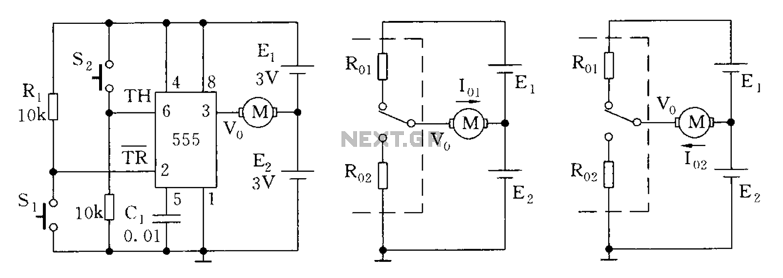
The 555 timer in bistable mode has fewer applications compared to its stable and monostable modes. Bistable mode refers to the circuit configuration based on the R-S (Reset-Set) trigger mode. An example of this is a micro-motor reversing control...
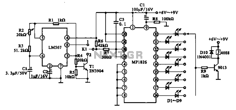
A precision circuit utilizing the LM567 timer, specifically the MPI826, where the LM567 functions as a dual-band oscillator. The MP1826 serves as a divider in the circuit, allowing the output signal from the LM567 to achieve extended timing. The...