
Nixie Clock Project

For professional applications, a special transformer is recommended to supply the required voltages, or at least an isolated 1:1 ratio separation transformer. In regions with a low mains voltage of 110 VAC, a shock from a live wire may be survivable. However, in high voltage areas, such as Germany with 230 VAC, accidental contact with a grounded surface can be fatal. A 1:1 transformer isolates input from output voltage, ensuring that while the 230 VAC input remains the same, there is no direct connection to ground when touching any wire. Caution is still necessary, as touching both wires simultaneously can result in serious injury. Separation transformers are typically large, heavy, and costly, though in this case, only a few watts are required, allowing for the construction of a custom separation transformer using two small transformers connected "back to back."
These transformers can be inexpensive printed circuit type transformers rated for at least 4 VA (Volt-Amperes), featuring a 230 V primary input and a 12 V / 300 mA output. If these specific transformers are unavailable, alternatives with 15 VAC or 8 VAC outputs can be used, as the intermediate voltage is less critical and is primarily for the logic board. It is important that the transformer connected to the AC mains is the larger of the two; a 10 Watt transformer should not be run from a 5 Watt transformer in this configuration, as it could overload the smaller transformer.
For the low voltage circuit, four 1N4001 diodes can be replaced with a block rectifier such as the B40-C1000. For the high voltage section, four 1N4007 diodes can be substituted with a B1000-C125 rectifier bridge, which must handle continuous operation at a minimum of 350 V, with a recommended minimum rating of 1N4004 (400V). A 100 KOhm resistor in parallel with a 10 µF / 350 V capacitor in the high voltage circuit aids in discharging the capacitor safely when no load is present. Additionally, for enhanced functionality, a 1 KOhm resistor can be added to the +12V output in series with a red LED for visual indication.Before Light-Emitting Diodes (LEDs) and Liquid Crystal Displays (LCDs) the electronic industry used cold-cathode tubes for displaying numbers, symbols and even characters. Even though they are called "tubes" they differ from "radio tubes" by having no heater wire to heat the cathode - and therefore run much colder.
They do have a glass envelope bu t unlike to (most) tubes they are not empty: they are filled with a gas compound, mainly neon gas. If you apply a voltage between the anode (+ pole) and one of the cathodes (- poles) the character-shaped cathode is covered with a pink to orange discharge glow. "NIXIE" was a trademark from Burroughs Corp. for their numeric display tubes. It is rumoured that they invented this kind of tube - or at least they got patents for it. There were many different types of these tubes: viewed from the side, viewed from the top, small ones, big ones, giant sized, types where a neon glows through a character-shaped mask and arrays of multiple nixies with multiplexed wires.
Even early "multi-segment" types were available, capable to display letters like the later LED 7-segment arrays. the voltage drops across the current-limiting resistor when one of the cathodes K0 - K9 is tied to GND.
The corresponding number-shaped cathode is then covered with a pink to orange glow. The values for the minimum U Well. the professional approach is to have either a special transformer for the required voltages or at least an isolated 1:1 ratio separation transformer. If you live in the "low voltage" areas of the world where 110 VAC is the usual AC mains voltage you may survive a shock from the life wire.
If you life in the "high voltage" areas like here in Germany the 230 VAC line voltage will surely kill you if you accidentially happen to be good grounded. A 1:1 transformer isolates the input voltage from the output voltage so you are not directly connected to AC mains.
The 230 VAC that goes in comes out as 230 VAC - but you have no connection to Earth (GND) when touching any wire. You are -nontheless- toasted if you touch both wires at one time. Separation transformers are usually big, heavy and expensive. Not as expensive as your life of course, but enough to blow a budget. In our case however we don`t need Kilowatt capabilities. A few Watts will do - so we can build our own separation transformer by simply using two small transformers "Back to Back".
The transformers can be simple, relatively cheap print-type transformers with greater 4 Watts output power. The ones I used on my prototype clock are rated 4 VA (Volt-Amperes) with a single 230 V primary input and a single 12 V / 300 mA output.
If you cannot get those - take two with e. g. 15 VAC or two with 8 V AC. The "intermediate voltage" between the two is of lesser importance, it is used for the logic board only. But at least the "one on the right side" must have a 230 V coil. If you have two different transformers: the bigger (stronger) one must be the one connected to AC-mains.
You cannot run a 10 Watt transformer from a 5 Watt type back to back for example. The 10 Watt has a lower resistance for the secondary coil - and the 5 Watt secondary coil is then overloaded. At least when you add load to it. It may work for some time however, but not reliably. The 4 diodes 1N4001 for the low voltage circuit can be replaced by a block rectifier like the B40-C1000 for instance; the 4 diodes 1N4007 for the high voltage part can be substituted by e.
g. a B1000-C125 rectifier bridge. This rectifier(s) must be capable to run continously with 350 V at least, so the minimum were a 1N4004 (rated 400V). Other than that there are no secrets in that circuit. The 100 KOhms parallel to the 10 µF/ 350 V capacitor in the HV part helps - for safety - discharging the capacitor when no load is placed across the output.
That`s all. For your own pleasure you may add a 1 KOhms resistor at the +12V output and a red LED. to remi 🔗 External reference
Related Circuits
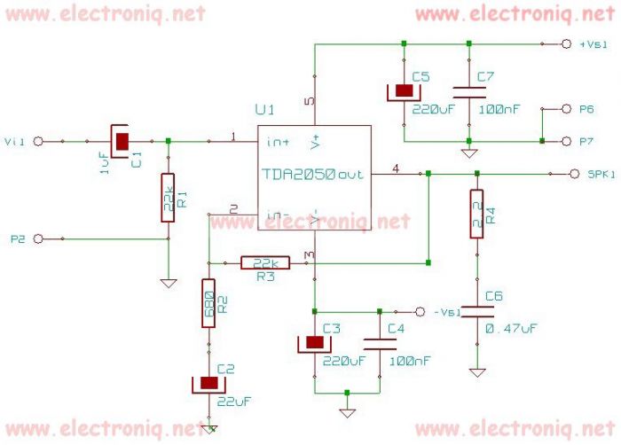
The TDA2050 integrated circuit can be used to design a simple high-fidelity audio power amplifier, intended for use as a Class AB audio amplifier. Due to its high power capabilities, the TDA2050 audio power amplifier can deliver up to...
The MM5314 is a monolithic MOS integrated circuit that incorporates P-channel low threshold enhancement mode and ion implanted depletion mode devices. It features an internal multiplex oscillator, fast and slow set controls, a single power supply, 7-segment outputs, leading...
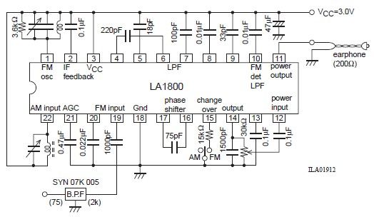
This portable AM/FM radio circuit is designed using the LA1800 integrated circuit (IC) along with several external components. The circuit diagram illustrates that the LA1800, manufactured by Sanyo Semiconductors, requires only a few additional components. The output signal is...
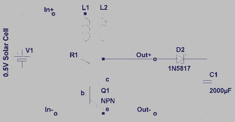
A steam engine-powered carousel project that utilizes the Joule Thief circuit. This project combines the classic charm of a steam engine with the innovative Joule Thief circuit, creating a unique carousel that operates efficiently. The steam engine serves as the...
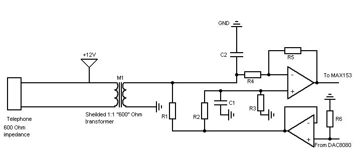
A simple non-commercial grade multiplexer compatible with telephones. It will support four telephone lines and will multiplex over one cable. The topic was free of choice but had to be oriented around the theme of "PrG©vision" (prediction). As anticipated,...
CMOS logic integrated circuits are highly versatile devices commonly utilized in modern electronic circuits. Testing these circuits with a standard multi-meter can be challenging due to the involvement of both static and pulsing voltages. A voltage reading of half...