
electronic combination lock circuit
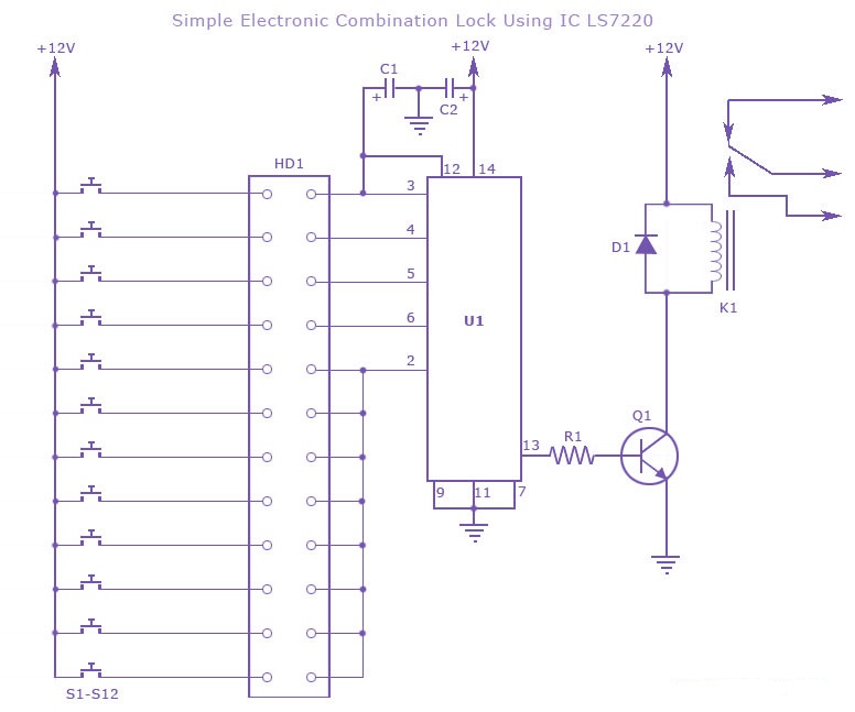
The electronic combination lock circuit utilizing the LS7220 IC is designed for secure access control, allowing users to unlock a device or door by entering a specific four-digit code. The LS7220 is a versatile integrated circuit that simplifies the implementation of keypad-based entry systems. The circuit's operation begins when the user presses keys on the keypad. Each key corresponds to a specific digit in the combination, which is wired to the designated pins of the LS7220.
To set the combination, the four keys representing the desired code must be connected to pins 3, 4, 5, and 6 of the IC. The remaining keys on the keypad are connected to pin 2, which serves as a reset input. This design ensures that if any unselected key is pressed, the system will reset, and the user must re-enter the entire combination.
The relay output is activated only when the correct sequence of digits is entered. This output can control various devices, such as electronic locks, alarms, or other mechanisms that require secure access. The duration for which the relay remains activated is adjustable by changing the capacitance of capacitor C1. A larger capacitance value will result in a longer activation time, which can be beneficial for applications requiring extended access.
In summary, this combination lock circuit is a practical solution for electronic access control, providing flexibility in code configuration and reliable operation through the use of the LS7220 IC and a simple relay mechanism. The design can be adapted for various applications, making it a valuable tool in electronic security systems.a simple electronic combination lock using IC LS 7220. This circuit uses a relay for controlling any type of device when the combinations of four digits are pressed. Keypads are used as input here to enter the digits and the correct combination will activate the relay and the door or deice can be operated.
The combinat ion can be set here by connecting the appropriate keys to the pins 3, 4, 5 and 6 of the IC through Header. Unselected keys are connected to the pin 2. For example if 4568 is your combination then it is to be connected to 3, 4, 5 and 6th pins and rest of the keys are connected to pin 2.
Thus any four key combination can be created using this. The 2nd pin of this IC was reset so whenever any other keys connected to pin 2 is pressed it will reset the device and the digits have to be re-entered. When the correct combination is pressed the output will be activated for a preset time determined by the capacitor C1.
Increase C1 value to increase on time. Using this circuit you can really construct a high efficient lock system. 🔗 External reference
Related Circuits
This is a range of IF signal circuits that may be of interest to radio hobbyists and professionals alike. Transistors T1 and T2 form an astable multivibrator oscillating in the audio frequency range of 1 to 2 kHz. An...

The i-St@r presents a simple mini audio amplifier circuit schematic utilizing the LM386 low voltage audio power amplifier IC. This circuit is designed to power medium-sized speakers from a music player that typically drives only earphones (LM386 headphone). The...
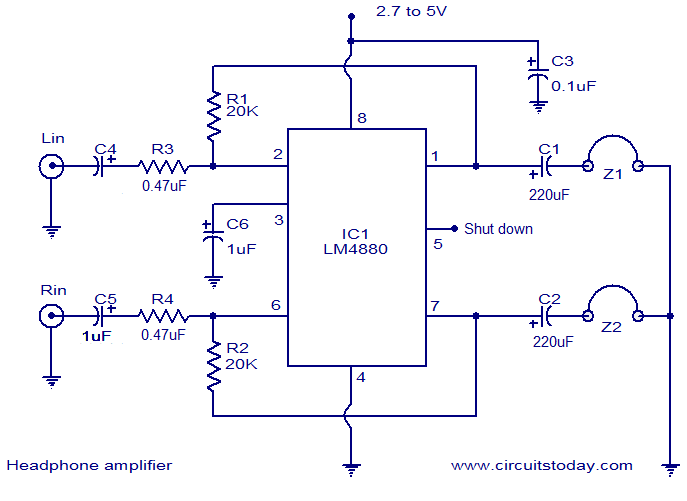
The LM4880 is a high-fidelity dual audio amplifier integrated circuit (IC) from National Semiconductors. This IC is specifically designed to deliver high-quality audio output with a minimal number of external components. The LM4880 can provide 250mW per channel into...
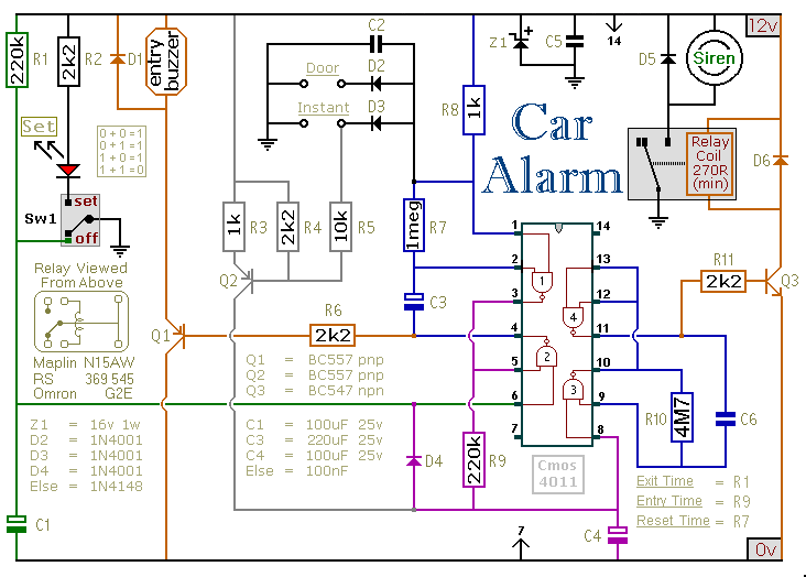
This car alarm circuit includes exit and entry delays, an instant alarm zone, an intermittent siren output, and automatic reset. By incorporating external relays, it is possible to immobilize the vehicle and activate the flashing lights. The car alarm circuit...
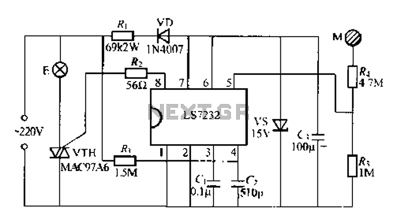
Figure (a) illustrates a general inverting amplifier circuit, which includes a 100k potentiometer as a feedback resistor connected in series between the input terminal and the inverting input to compensate for the DC bias current. The potentiometer (Rp) should...

This homemade metal detector circuit will assist in locating objects made of materials with relatively high magnetic permeability. It is not suitable for detecting certain metals. This metal detector circuit operates on the principle of electromagnetic induction, utilizing a coil...