
Homemade metal detector circuit

This metal detector circuit operates on the principle of electromagnetic induction, utilizing a coil of wire to generate an oscillating magnetic field. When a conductive or ferromagnetic object enters this field, it induces a change in the magnetic flux, which can be detected by the circuit.
The core components of the circuit include a transmitter coil, which emits the magnetic field, and a receiver coil, which detects the variations caused by nearby metallic objects. A simple oscillator circuit, often based on a 555 timer IC, can be employed to generate the required frequency for the transmitter. The frequency is typically set in the range of a few kHz to ensure effective detection of various metals.
Additional components may include a potentiometer for tuning the sensitivity of the detector, allowing the user to adjust the circuit for different types of metals or ground conditions. A simple audio output device, such as a piezo buzzer, can provide an audible indication when a metal object is detected.
Power supply considerations are also essential; the circuit can be powered by batteries or a DC power source, depending on the design requirements. Proper grounding and shielding techniques should be implemented to minimize interference from environmental noise, which can affect the performance of the detector.
Overall, this homemade metal detector circuit is a practical project for electronics enthusiasts, providing a hands-on experience in understanding basic principles of electromagnetism and circuit design.This homemade metal detector circuit will help you find objects composed of materials with relatively high magnetic permeability. It is not suitable for bu.. 🔗 External reference
Related Circuits
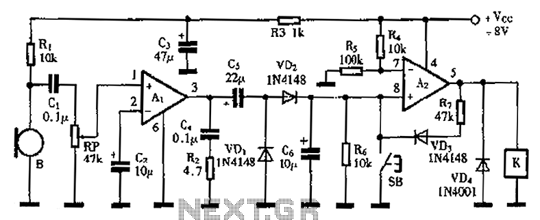
A practical voice-activated switch is presented. An A1 amplifier is connected to a conventional microphone (B) that picks up the audio control signal, which is then amplified. After amplification, the signal passes through components C5, VD1, and VD2, forming...

This house FM transmitter for your stereo or any other amplifier provides a strong signal strength up to a distance of 500 meters with a power output of about. This FM transmitter is designed to enhance audio transmission capabilities for...

The BISS0001 is a high-performance integrated circuit designed for sensor signal processing. When combined with pyroelectric infrared sensors and a minimal number of external components, it forms a passive pyroelectric infrared switch. This device can automatically and quickly activate...

The following circuit illustrates a curtain control circuit diagram. This circuit is based on the 555 integrated circuit (IC). Features include a switch for manual control, the IC, and additional components. The curtain control circuit utilizes the 555 timer IC...
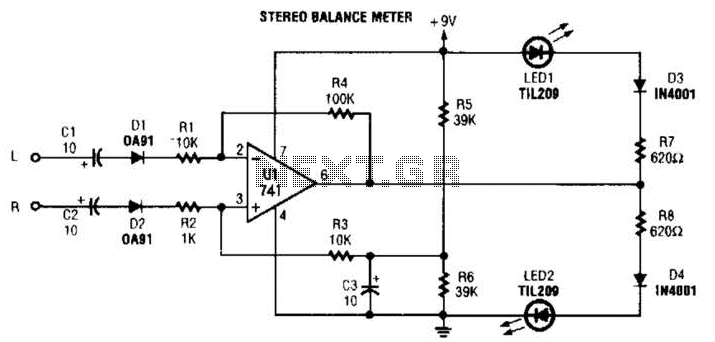
When the L and R signals are equal, no output is present from U1, and pin 6 is at a steady 4.5 V. Unbalanced audio causes the LEDs to vary in brightness, which indicates a difference that corresponds to...

This is a low-cost protection circuit designed to safeguard electrically operated home appliances, such as TVs, DVD players, refrigerators, and other devices, during sudden power outages and the subsequent restoration of mains supply. Appliances like refrigerators and air conditioners...