
Simple portable Audio power amplifier circuit using LM386 IC
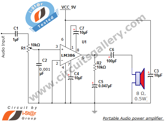
The LM386 audio amplifier circuit is a versatile and efficient solution for various audio amplification needs. The circuit design is straightforward, making it accessible for hobbyists and professionals alike. The LM386 IC is favored for its low power consumption and ability to operate effectively with limited supply voltage, which is particularly advantageous in battery-operated devices.
In practical applications, the circuit can be configured to drive speakers with impedances typically ranging from 4 to 8 ohms, making it suitable for a variety of small to medium speakers. The gain control feature allows for customization of audio output levels, enabling users to tailor the amplifier's performance to specific requirements.
The use of capacitors C1 and C6 is critical in ensuring that only audio signals are amplified, preventing any DC offset that could potentially damage connected speakers or result in poor audio quality. Capacitor C5 plays an essential role in maintaining audio fidelity by filtering out unwanted high-frequency noise, which can degrade the listening experience.
Overall, the LM386-based mini audio amplifier circuit is a reliable choice for enhancing sound output in portable devices and various audio applications, providing a practical balance of simplicity, effectiveness, and adaptability.Here i-St@r comes with thesimplest mini audio amplifier circuitschematicusing LM386 low voltage audio power amplifier IC. This circuit is applicable to power medium sized speakers from a music player that can only drive earphones (lm386 headphone).
The LM386 is a low voltage power amplifier IC designed for use in low voltage consumer applications. It can be used under battery operation and has a wide supply voltage range: 4V 12V or 5V 18V enabling us to use the circuit as a portable amplifier. Our simple audio amplifier has many applications, the common lm386 projects are AM-FM radio amplifiers, portable tape player amplifiers, intercoms, TV sound systems, line drivers, ultrasonic drivers, small servo drivers, power converters and much more.
The audio signal is connected to the circuit using a capacitor C1. This capacitor passes only audio, and blocks any direct current (DC) that may influence the biasing conditions of the amplifier. To make the LM386 a more flexible audio amplifier, two pins (1 and 8) are provided for gain control and gain adjustments.
With pins 1 and 8 open, the 1. 35 kW internal resistance sets the gain at 20 (26 dB). If a capacitor is placed from pin 1 to 8, bypassing the 1. 35 kW internal resistor, the gain will go up to 200 (46 dB). The resistor R2 and capacitor C5 forms a filter circuit, which prevents high frequency signals coming from the amplifier, most probably noise picked up or generated in the amplifying process of LM386 IC. The capacitor C6 connected at the output pin has the same function as the capacitor used in the input stage i.
e. to prevent direct current (DC) due to the biasing of LM385 amplifier IC, causing undesired operation of the speaker. 🔗 External reference
Related Circuits
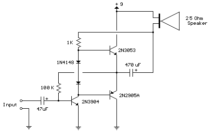
This circuit is similar to the one above but uses positive feedback to get a little more amplitude to the speaker. I copied it from a small 5 transistor radio that uses a 25 ohm speaker. In the circuit...
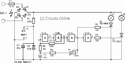
This is a design for a flashlight that two 220 V alternating lights can control. The flashlight uses only one IC. IC1a IC1c to be used for the flashing signal generation. The output of IC1c thyristor T1 is controlled,...
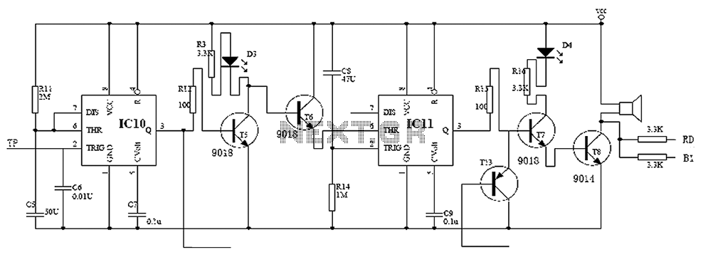
Child lock voltage comparator 555 monostable circuit, a counter, JK flip-flop, UPS power supply design digital logic circuit, electronic door control, and various additional circuitry to ensure the safety circuit can operate with a high safety factor. The circuit...
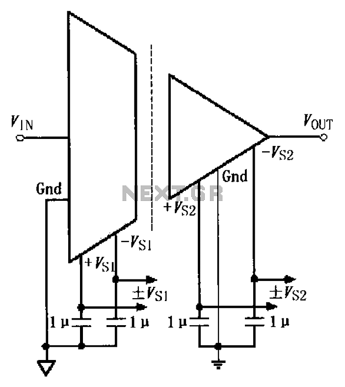
The basic connection circuit for the ISO122/124 includes power and signal connections. Each supply terminal of the ISO122/124 must be equipped with a 1 µF tantalum capacitor serving as a bypass filter. It is important to position the printed...
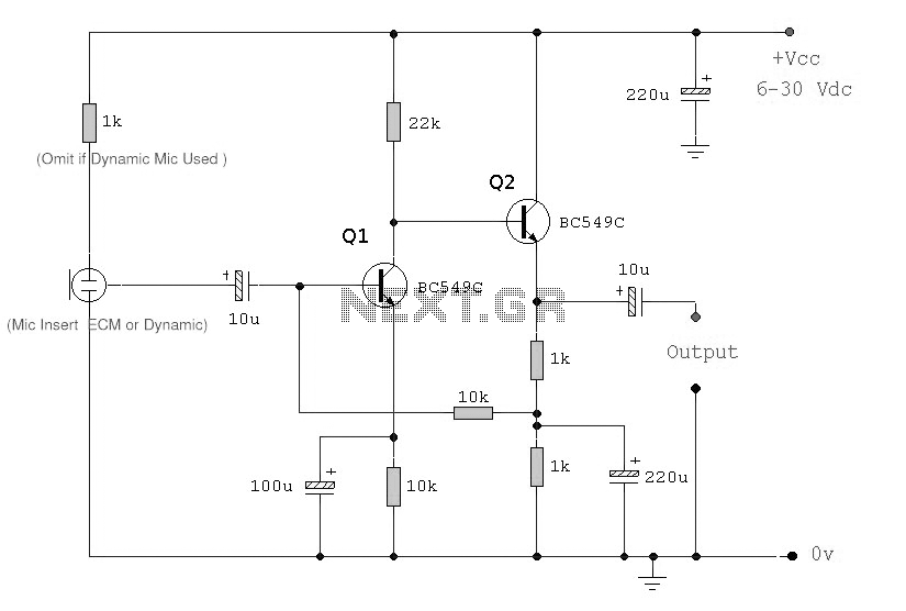
This circuit diagram represents an ECM Mic Preamplifier. It is a microphone amplifier compatible with Electret Condenser Microphones (ECM). The preamplifier exhibits an excellent dynamic range, capable of handling audio levels from a whisper to a scream; however, caution...
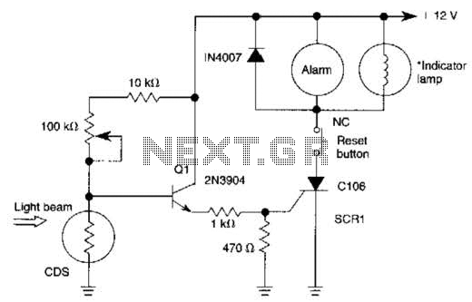
When the light beam that falls on the CDS photocell is interrupted, the transistor (EN3904) conducts, triggering SCR1 (CI06) and activating the alarm bell. SI resets the SCR. The alarm bell should be a self-interrupting electromechanical type. The lamp...
Warning: include(partials/cookie-banner.php): Failed to open stream: Permission denied in /var/www/html/nextgr/view-circuit.php on line 713
Warning: include(): Failed opening 'partials/cookie-banner.php' for inclusion (include_path='.:/usr/share/php') in /var/www/html/nextgr/view-circuit.php on line 713