Electronic crowbar for AC or DC lines
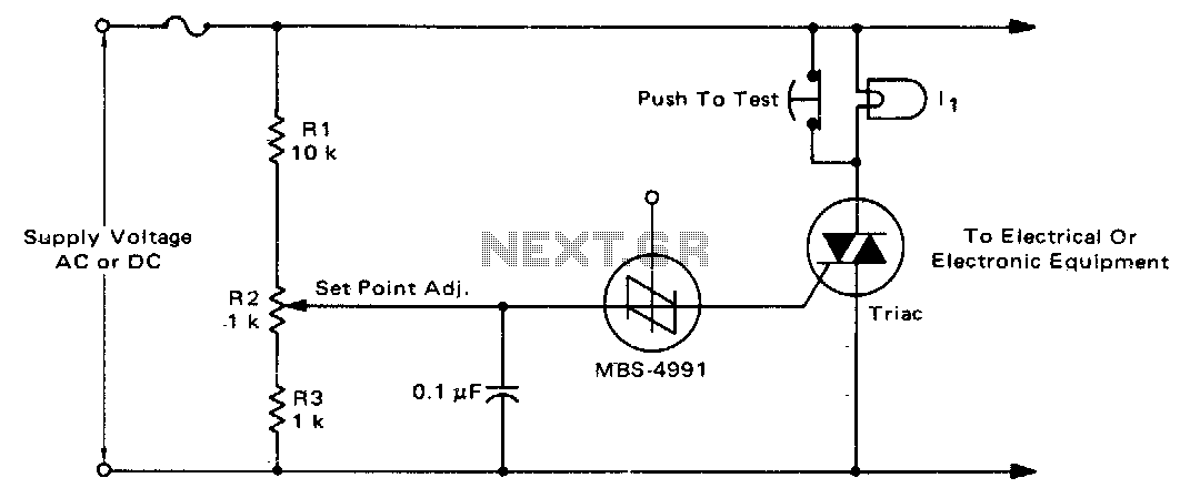
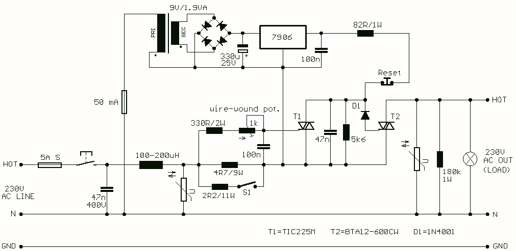
For positive protection of electrical or electronic equipment, this circuit is designed to guard against excessive supply voltage. An electronic crowbar circuit can rapidly create a short circuit across the power lines due to improper switching, wiring issues, short circuits, or regulator failures, effectively reducing the voltage across the protected device to nearly zero and blowing a fuse. The triac and SBS are bilateral devices, making the circuit applicable for both AC and DC supply lines. The values for R1, R2, and R3 allow for the adjustment of the crowbar operating point within a range of 60 to 120 volts DC or 42 to 84 volts AC. These resistor values can be modified to accommodate different ranges of supply voltages. The voltage rating of the triac must exceed the highest operating point established by R2. A low-power incandescent lamp, with a voltage rating matching the supply voltage, can be utilized to verify the set point and functionality of the unit by opening the test switch and adjusting the input or set point to trigger the SBS. An alarm unit, such as the Mallory Sonalert, may be connected across the fuse to provide an audible indication of crowbar action. Note that this circuit may not respond to short, infrequent power line transients.
The electronic crowbar circuit serves as a vital protective measure for electrical and electronic devices by preventing damage from overvoltage conditions. The core components include a triac, which functions as a switch that can handle AC and DC voltages, and a silicon-controlled rectifier (SBS) that provides bilateral conduction. The circuit's design allows for rapid response to overvoltage situations, with the triac shorting the power supply when the voltage exceeds a predetermined threshold, thereby protecting downstream components.
The adjustable resistors R1, R2, and R3 play a crucial role in setting the operational voltage limits. By selecting appropriate resistor values, the user can tailor the circuit to activate within specific voltage ranges suitable for the application. For instance, when configured for a 120V DC system, the resistors can be adjusted to ensure that the crowbar activates before the voltage reaches a damaging level.
In practical applications, the inclusion of a test switch enables the technician to simulate overvoltage conditions for testing purposes. By opening the switch and adjusting the input voltage, the technician can observe the crowbar's response, ensuring that the protection mechanism is functioning correctly. The use of an incandescent lamp as a load allows for a visual indication of circuit operation, simplifying troubleshooting.
Additionally, the integration of an audible alarm, such as the Mallory Sonalert, enhances the circuit's utility by providing immediate feedback when the crowbar activates. This feature is particularly useful in industrial settings where visual monitoring may not be feasible.
It is important to note that while this circuit effectively protects against sustained overvoltage conditions, it may not respond to transient surges that occur infrequently. Therefore, for comprehensive protection strategies, it may be prudent to complement this crowbar circuit with other protective devices, such as surge protectors, to mitigate the risk of transient events.For positive protection of electrical or electronic equipment, use this against excessive supply voltage. Due to improper switching, wiring, short circuits, or failure of regulators, an electronic crowbar circuit can quickly place a short circuit across the power lines, thereby dropping the voltage across the protected device to near zero and blowing a fuse.
The triac and SBS are both bilateral devices, the circuit is equally useful on ac or dc supply lines. With the values shown for Rl, R2, and R3, the crowbar operating point can be adjusted over the range of 60 to 120 volts dc or 42 to 84 volts ac.
The resistor values can be changed to cover a different range of supply voltages The voltage rating of the triac must be greater than the highest operating point as set by R2, II is a low power incandescent lamp with a voltage rating equal to the supply voltage. It may be used to check the set point and operation of the unit by opening the test switch and adjusting the input or set point to fire the SBS.
An alarm unit such as the Mallory Sonalert may be connected across the fuse to provide an audible indication of crowbar action. (This circuit may not act on short, infrequent power line transients).
