
Electronic Metronome Generates Mechanical Sound
The metronome circuit is designed to produce rhythmic sounds that assist musicians in maintaining a consistent tempo. The mechanical sound character is typically achieved through the use of a pendulum mechanism or a similar oscillating component that generates audible clicks at regular intervals.
Key components of the metronome circuit may include an oscillator, a control circuit for adjusting the tempo, and a sound-producing element such as a speaker or a mechanical striker. The oscillator generates a square wave signal, which is used to trigger the sound-producing element. The tempo can be adjusted by varying the frequency of the oscillator, allowing the user to set the desired beats per minute (BPM).
The circuit may also incorporate additional features such as visual indicators, like LED lights, that flash in sync with the metronome's beats. This can further aid musicians in keeping time, especially in noisy environments where the audible clicks may be difficult to hear.
In terms of power supply, the metronome circuit can be powered by batteries or an external power source, depending on the design requirements. Compact and portable designs are often preferred, enabling musicians to carry the device easily during practice sessions.
Overall, the mechanical sound character of the metronome circuit not only adds a nostalgic charm but also serves a practical purpose in enhancing musical accuracy and enjoyment.This is a metronome circuit that has mechanical sound character. The metronome that has mechanical sound character will make our life more fun and it would be . 🔗 External reference
Related Circuits
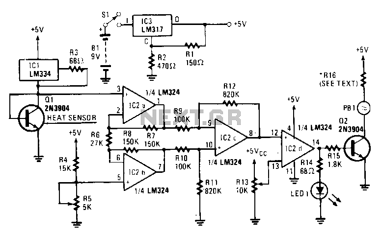
The sensing element Q1 is a 2N3904 general-purpose NPN transistor, although any general-purpose NPN unit in a TO-92 style case will suffice. IC1, an LM334, provides Q1 with a constant current that remains stable regardless of temperature variations. An...
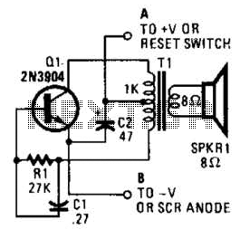
This is a simple low-level noise maker that is ideally suited for certain alarm applications. When the sounder is located in another part of the building, the sound level is loud enough to be heard but is not loud...
The following circuit illustrates a 14 Watt Compact Fluorescent Electronic Ballast Circuit Diagram. Features: it is similar to a 16 Watt circuit, 14 Watt. The 14 Watt Compact Fluorescent Electronic Ballast Circuit is designed to efficiently drive compact fluorescent lamps...
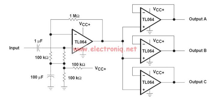
This audio distribution electronic project circuit diagram is designed using the TL064 or TL06 operational amplifiers and some other common electronic parts. The audio distribution circuit utilizes TL064 or TL06 operational amplifiers, which are quad op-amps known for their low...
Over 1400 top electronics projects and electronic circuits with photos, datasheets, and easy-to-read schematics, along with explanations of how they work and how to build them. The collection comprises a vast array of electronics projects suitable for enthusiasts and professionals...
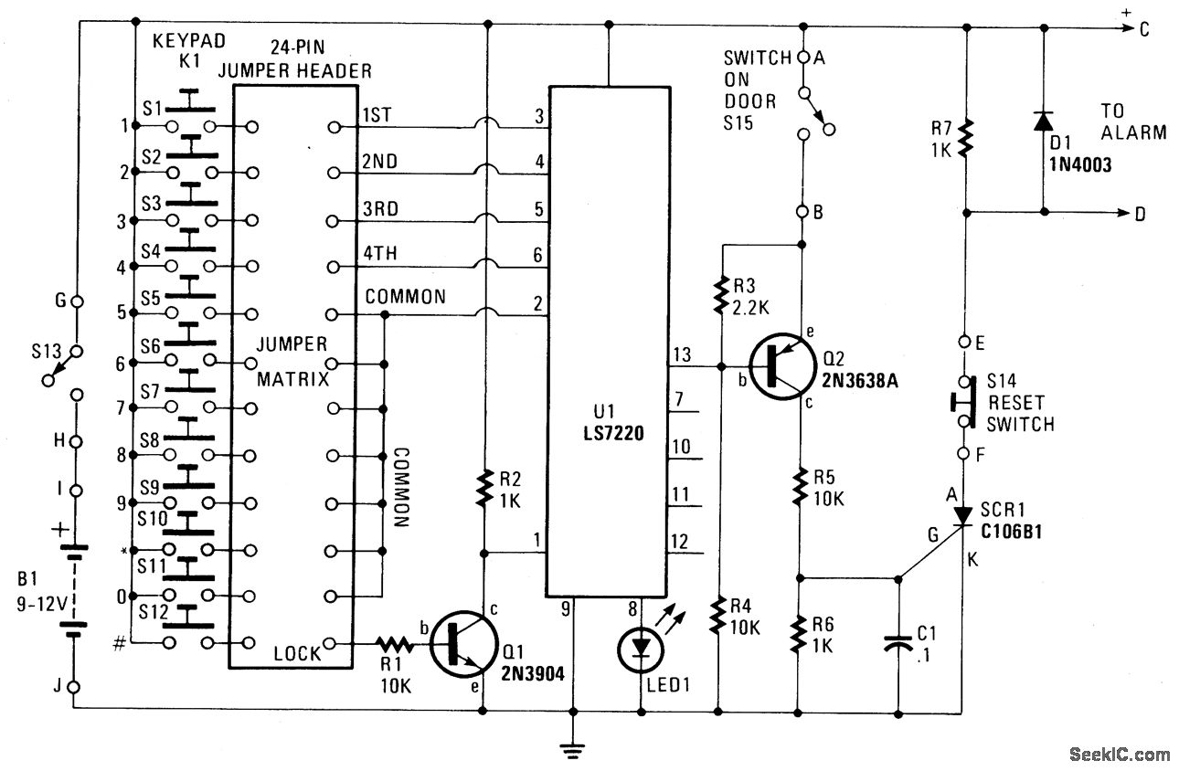
When button S12 is pressed, a positive voltage supplied through resistor R1 is applied to the base of transistor Q1, activating it. When Q1 is in the conducting state, pin 1 of U1 is connected to ground (low) or...
Warning: include(partials/cookie-banner.php): Failed to open stream: Permission denied in /var/www/html/nextgr/view-circuit.php on line 713
Warning: include(): Failed opening 'partials/cookie-banner.php' for inclusion (include_path='.:/usr/share/php') in /var/www/html/nextgr/view-circuit.php on line 713