
Electronic Mailbox Front Door With 2N3906 Transistor
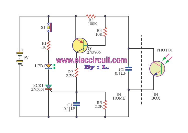
The integrated electronic mailbox circuit is designed to enhance the functionality of a front door system. It typically includes several key components: a microcontroller, a photo detector, and various sensors to detect door status and light conditions.
The microcontroller serves as the central processing unit, receiving input from the door sensor and the photo detector. When the front door is opened, the door sensor triggers the microcontroller, which can activate a notification system, alerting the homeowner of the door's status. This could be in the form of a visual indicator, such as an LED, or an auditory signal, such as a chime.
The photo detector plays a crucial role in this circuit. It is designed to detect ambient light levels and can activate or deactivate certain functions based on these levels. For instance, if the cabinet photo detector detects sufficient light, it could signal the microcontroller to enter a low-power state or to deactivate the notification system during the day, thereby conserving energy. Conversely, in low-light conditions, the system could remain active to ensure that alerts are received when the door is opened.
The circuit may also include additional features such as a timer to manage how long the system remains active after the door has been opened, and a power management module to ensure efficient operation. Overall, this integrated electronic mailbox circuit provides a practical solution for monitoring door activity while minimizing unnecessary notifications and conserving energy.This is a integrated electronic mailbox circuit diagram, A front door open.And when people open. When the cabinet photo detector attached to the light, it will .. 🔗 External reference
Related Circuits
The saying goes "dead ringworm surgical, medical dead asthma." This example describes an electronic anti-asthmatic device that produces high-voltage stimulation pulses, which can serve as an adjunct therapy for patients suffering from cough. The circuit consists of a self-excited...

The following circuit illustrates a VHF pre-amplifier circuit diagram. This circuit utilizes the BFS17 transistor. Features: designed for VHF applications. The VHF pre-amplifier circuit is essential for enhancing weak radio frequency signals in the VHF (Very High Frequency) range, typically...
This circuit operates with a 12V supply connected to a motor, utilizing transistors TIP 142 and TIP 147. Each transistor is controlled by a high (5V) or low (0V) signal through a 1kΩ resistor. The diodes used in the...
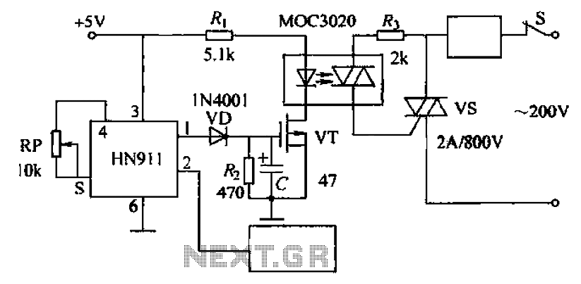
Automatic door control circuit diagram. It utilizes a pyroelectric infrared detection module, HN911, for human motion detection. A variable resistor (potentiometer) is used to adjust the delay time controlled by a transistor (VT). An optocoupler (MX: 3020) provides AC...
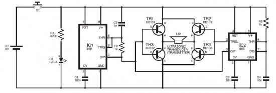
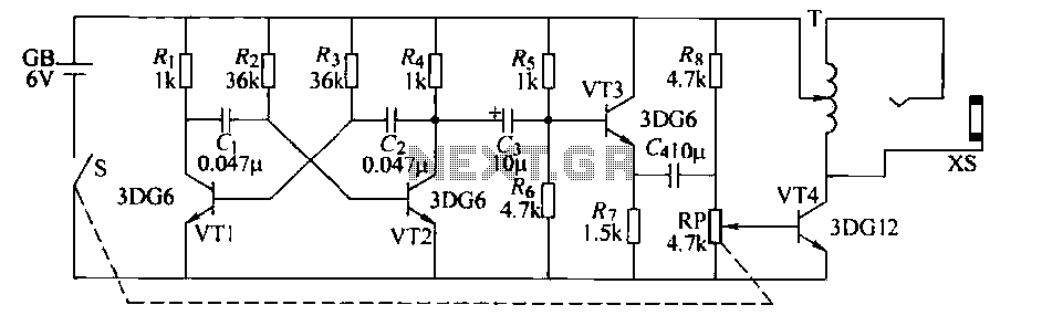
The electronic dog repellent circuit diagram below features a high-output ultrasonic transmitter designed primarily to function as a repeller for dogs and cats. The electronic dog repellent circuit utilizes an ultrasonic transmitter to emit sound waves at frequencies above the...
This project is built on the third section of the PC board, identified by "SIREN" and "Project 5." You will notice the similarity between this circuit and the LED FLASHER circuit from project 2. The only differences are the...
Warning: include(partials/cookie-banner.php): Failed to open stream: Permission denied in /var/www/html/nextgr/view-circuit.php on line 713
Warning: include(): Failed opening 'partials/cookie-banner.php' for inclusion (include_path='.:/usr/share/php') in /var/www/html/nextgr/view-circuit.php on line 713