
electronic door release
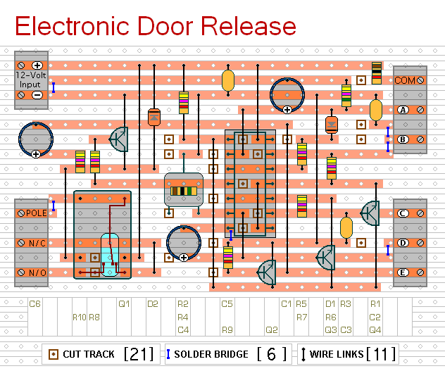
The circuit comprises a microcontroller that processes the input from a keypad where the user enters the four-digit code. The microcontroller is programmed to recognize the specific sequence of digits. Upon successful entry of the correct code, the microcontroller sends a signal to a relay driver circuit, which then activates the relay. The relay serves as a switch that can handle higher voltage and current loads, allowing it to control the door-release mechanism effectively.
The system should include a power supply circuit that can either be connected to mains power or utilize a battery for operation. If a battery is used, a low-power microcontroller is recommended to ensure long battery life. The circuit may also incorporate a voltage regulator to maintain stable operation despite variations in power supply.
Additional features may include an LED indicator to provide visual feedback when the relay is energized and a buzzer that sounds upon successful code entry or incorrect attempts. For security purposes, the system can be designed to limit the number of incorrect entries before locking out further attempts for a specified duration.
In terms of layout, the circuit should be designed to minimize the distance between the microcontroller, keypad, and relay to reduce the risk of interference and ensure reliable operation. Proper decoupling capacitors should be placed near the power pins of the microcontroller to filter out noise. The relay contacts should be rated appropriately for the load they will control, and the use of flyback diodes across the relay coils is essential to protect the microcontroller from voltage spikes when the relay is de-energized.This circuit is designed to operate an electrical door-release mechanism - but it will have other applications. When you enter the four-digit code of your choice - the relay will energize for a preset time period.
Use the relay contacts to power the release mechanism. The standby current is virtually zero - so battery power is a realistic option.. 🔗 External reference
Related Circuits

The input capacitor is used for low-frequency cut-off, with a standard value of 0.1 µF, resulting in a cut-off frequency of approximately 16 Hz. The input capacitor plays a critical role in electronic circuits, particularly in signal processing and audio...
The circuit allows up to eight participants, each assigned a unique number from 1 to 8. The display indicates the number of the contestant who presses their button before the others. Simultaneously, a buzzer sounds. Both the display and...
For a fixed frequency transmitter, a common method is to use a resonant quartz crystal in a crystal oscillator to establish the frequency. In transmitters where the frequency must be variable, several options are available. It is often the...
The example circuit and code should be sufficient to begin without delving into additional details. A rotary encoder is an electromechanical component with a shaft that records rotation and converts it into electrical pulses to indicate the direction of...
The power supply unit (PSU) in question does not appear to be exceptionally large. Eagle software should be capable of managing these dimensions. The focus was more on finding an alternative that may already include the necessary components and...
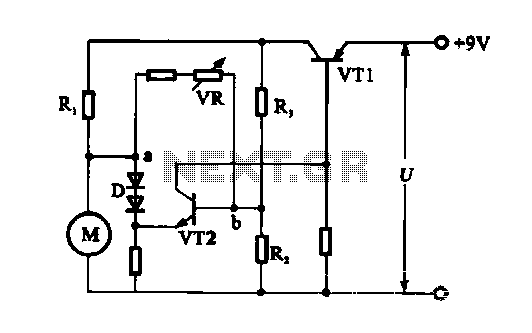
The electronic circuit for steady speed motor applications utilizes an automatic remote control system to regulate the motor power supply, thereby achieving consistent speed control. The circuit diagram illustrates a DC motor connected to the system. Given that the...