
Electronics/Transmitter design
The design of a variable frequency transmitter involves several critical components and configurations to ensure efficient operation and signal integrity. The core of the transmitter typically consists of a crystal oscillator, which stabilizes the frequency for fixed frequency applications. For variable frequency applications, additional circuitry may include varactor diodes or phase-locked loops (PLLs) that allow for fine-tuning of the output frequency based on the modulation requirements.
The amplifier stages are crucial in shaping the output signal. The use of push-pull configurations helps to minimize distortion and improve linearity, particularly in the context of harmonic generation. By optimizing the amplifier stages to operate at harmonic frequencies, the transmitter can achieve greater output power and efficiency. The choice of using tetrodes is significant due to their lower capacitance, which enhances stability and performance in high-frequency applications.
Modulation techniques play a vital role in the transmission of information. For analog signals, AM and FM modulation methods are prevalent, while digital signals require more sophisticated techniques such as FSK or OOK, which accommodate the discrete nature of digital data. The feedback mechanism employed in the modulation stage is essential for maintaining signal fidelity, especially when utilizing Class C amplifiers that inherently introduce non-linearities.
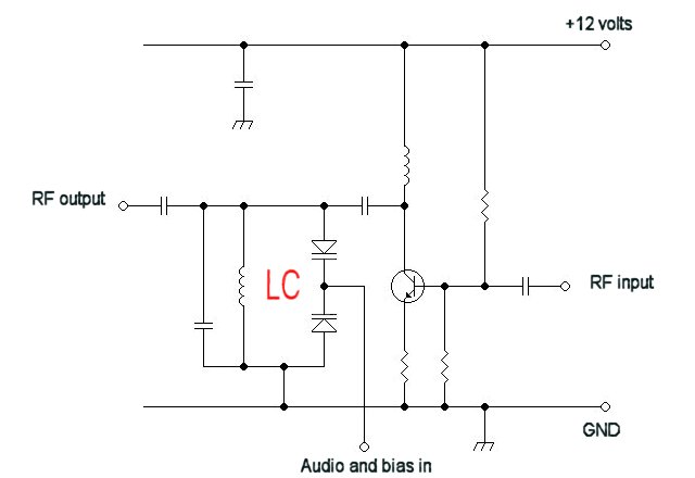
In practical applications, considerations such as power supply requirements, component selection, and overall system design must be addressed to ensure reliable operation. The integration of a feedback system not only enhances the modulation quality but also allows for the efficient use of power, which is particularly important in mobile and portable transmitter designs. Overall, the design and implementation of variable frequency transmitters require a careful balance of various engineering principles to achieve optimal performance.For a fixed frequency transmitter one commonly used method is to use a resonant quartz crystal in a Crystal oscillator to fix the frequency. For transmitter where the frequency has to be able to be varied then several options can be used. It is often the case for VHF transmitters that it is not possible to operate the crystal controlled or variabl
e frequency oscillator at the frequency of the final output. Also, for reasons including frequency stability, it is better to multiply the frequency of the free running oscillator up to the final frequency which is required. If the output of a amplifier stage is tuned to a multiple of the frequency which the stage is driven with, the stage is optimised to give a larger harmonic output than that found in a linear amplifier.
In a push-push stage, the output will only contain the even harmonics. This is because the currents which would generate the fundamental and the odd harmonics in this circuit (if one valve was removed) are canceled out by the second valve. Note that in these diagrams that the bias supplies and the neutralization have been omitted for clarity.
In a real system it is likely that tetrodes would be used as plate to grid capacitance in a tetrode is lower so making the stage less likely to be unstable. The task of many transmitters is to transmit some form of information using a carrier wave. This process is called modulation. There are many types of RF modulation, and the choice of modulation often depends on the type of information being transmitted.
For instance, audio information is continuous in time and value, and scaling by a constant (i. e. signal inversion, volume control) is acceptable, so AM and FM transmission work. But for digital communications, the signal is discrete in time and discrete in value, and inversion of the signal is unacceptable, so AM and FM are not (on their own) satisfactory. For digital communications, a modulation such as frequency shift keying (FSK) or on-off keying (OOK) over FM would be better.
The advantage of using a linear RF amplifier is that the smaller early stages can be modulated, which only requires a small audio amplifier to drive the modulator. The great disadvantage of this system is that the amplifier chain is less efficient, because it has to be linear to preserve the modulation.
Hence class C amplifiers cannot be employed. An approach which marries the advantages of low-level modulation with the efficiency of a Class C power amplifier chain is to arrange a feedback system to compensate for the substantial distortion of the AM envelope. A simple detector at the transmitter output (which can be little more than a loosely coupled diode) recovers the audio signal, and this is used as negative feedback to the audio modulator stage.
The overall chain then acts as a linear amplifier as far as the actual modulation is concerned, though the RF amplifier itself still retains the Class C efficiency. This approach is widely used in practical medium power transmitters, such as AM radiotelephones. One advantage of using class C amplifiers in a broadcast AM transmitter is that only the final stage needs to be modulated, and that all the earlier stages can be driven at a constant level.
These class C stages will be able to generate the drive for the final stage for a smaller DC power input. However in many designs in order to obtain better quality AM the penultimate RF stages will need to be subject to modulation as well as the final stage.
A large audio amplifier will be needed for the modulation stage, at least equal to the power of the transmitter output itself. Traditionally the modulation is applied using an audio transformer, and this can be bulky. Direct coupling from the audio amplifier is also possible (known as a cascode arrangement), though this usually requires quite a high DC supply voltage (say 30V or more), which is not suitable for mobile units.
A wide range o 🔗 External reference
Related Circuits
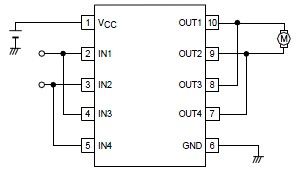
A simple forward-reverse motor control driver electronic circuit can be designed using the LB1948M, a two-channel low saturation voltage forward-reverse motor control driver IC. The LB1948M motor driver is suitable for use in 12V system products and can drive...
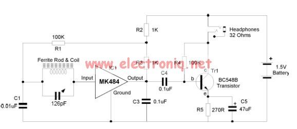
The MK484 AM radio circuit offers a comprehensive solution featuring an RF amplifier, detection, and an automatic gain control (AGC) circuit. It requires only a few external components to achieve high-quality AM tuning. The circuit has an input impedance...
The water resource is being transformed into a valuable and rare commodity. Consequently, promoting water-saving irrigation has become a priority for countries worldwide to address the water resource crisis and achieve agricultural modernization. This text proposes a cipher scheme...
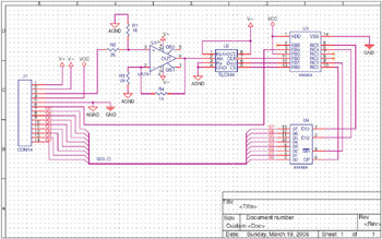
Mixed Analog/Digital Design Using Split Power and Ground Planes. The following example illustrates the design of a circuit that incorporates both analog and digital components. It features multiple power planes and a single ground plane that is divided into...
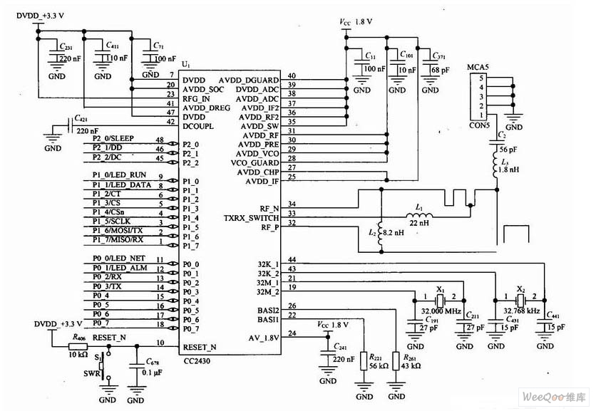
The development of advanced driving assistance systems and automotive electronics is increasingly reliant on interconnected technologies. A new radar system for reversing vehicles is designed to perform serial range finding and accurately measure the distance to obstacles, while also...
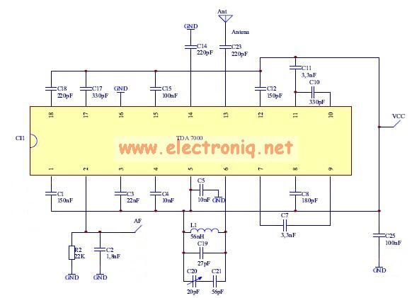
The TDA7000 features a Frequency-Locked-Loop (FLL) system with an intermediate frequency of 70 kHz, and selectivity is achieved through active RC filters. The only calibration required is for the resonant circuit associated with the oscillator, which is necessary for...
Warning: include(partials/cookie-banner.php): Failed to open stream: Permission denied in /var/www/html/nextgr/view-circuit.php on line 713
Warning: include(): Failed opening 'partials/cookie-banner.php' for inclusion (include_path='.:/usr/share/php') in /var/www/html/nextgr/view-circuit.php on line 713