
Electronic Door Release
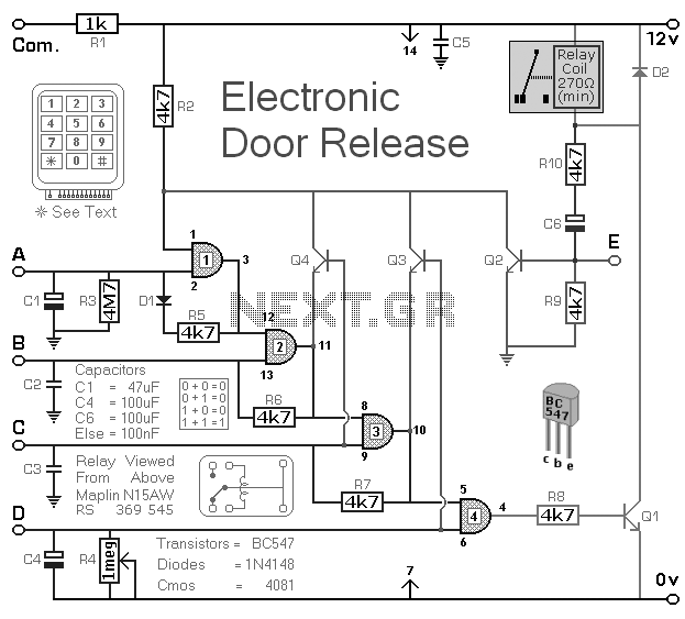
The electronic door release circuit serves as a secure access control system, allowing users to unlock a door by inputting a predetermined four-digit code. The core of the circuit typically includes a microcontroller, which processes the input code, and a relay module, which activates the door release mechanism upon successful code validation.
The circuit design begins with a keypad interface where users can enter the four-digit code. Each key press is detected by the microcontroller, which converts the input into a digital signal. The microcontroller is programmed with the correct code and logic to compare the entered code against the stored value.
Once the correct code is entered, the microcontroller sends a signal to the relay module. The relay, which acts as a switch, is energized, allowing current to flow to the door release mechanism. This mechanism can be an electric strike, magnetic lock, or any other compatible locking system. The relay remains activated for a predetermined duration, allowing sufficient time for the door to be opened.
Additional features may include an LED indicator to provide visual feedback on the status of the system, such as successful code entry or an error state. An audible buzzer can also be incorporated to signal incorrect attempts or to confirm successful unlocking.
For enhanced security, the circuit can be designed to limit the number of incorrect attempts before locking out further entries for a specific time period. This helps prevent unauthorized access through brute-force attempts.
The power supply for the circuit typically ranges from 12V to 24V, depending on the specifications of the relay and door release mechanism used. Proper attention must be given to the circuit layout to ensure reliable operation, including the use of appropriate resistors, capacitors, and protection diodes to safeguard against voltage spikes when the relay is activated.
In summary, this electronic door release circuit combines user-friendly access control with robust security features, making it suitable for various applications beyond just door entry, such as securing cabinets or restricted areas.Electronic Door Release Circuit This circuit is designed to operate an electrical door-release mechanism - but it will have other applications. Enter the four-digit code of your choice - and the relay will energize for the perio.. 🔗 External reference
Related Circuits
The following circuit illustrates a Dancing LEDs electronic circuit diagram. This circuit is based on the LM358 integrated circuit. Features: IC1A amplifies the signal. The Dancing LEDs circuit utilizes the LM358 operational amplifier to create a visually appealing light display....
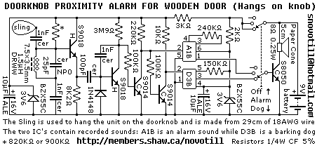
Reverse engineered circuit diagram of a popular retail doorknob alarm. It contains a small transmitter and the doorknob acts as an antenna so it will not work on a metal door. When a person comes close to the doorknob...
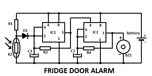
This fridge door alarm operates using a 3V battery supply and should be placed in a small box inside the fridge, near the lamp or close to the opening. The fridge door alarm circuit is designed to alert users...
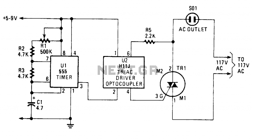
The blinking or flashing rate is determined by U1, a 555 timer integrated circuit. Its output, at pin 3, feeds U2, a H11J triac driver. That driver consists of an infrared LED that is coupled internally to a light-activated...
This modified Hartley oscillator can be utilized to attract new friends or serve as a replacement doorbell. The modified Hartley oscillator is a type of electronic oscillator that generates a continuous waveform, typically a sine wave, using an LC (inductor-capacitor)...

This circuit utilizes a CMOS integrated circuit to perform dual functions. The first two inverters serve as a digital audio oscillator, while the third inverter functions as a low-gain linear audio amplifier. The frequency of the oscillator increases with...
Warning: include(partials/cookie-banner.php): Failed to open stream: Permission denied in /var/www/html/nextgr/view-circuit.php on line 713
Warning: include(): Failed opening 'partials/cookie-banner.php' for inclusion (include_path='.:/usr/share/php') in /var/www/html/nextgr/view-circuit.php on line 713