
Electronic light flasher
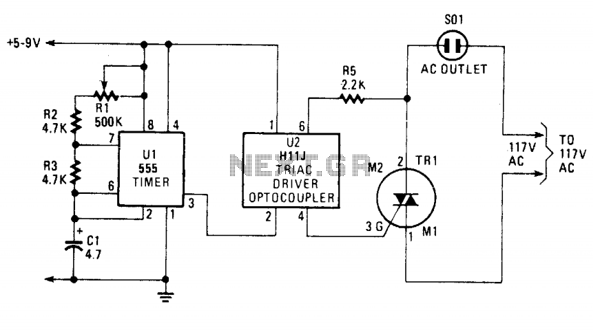
The circuit utilizes a 555 timer (U1) configured in astable mode to generate a continuous square wave output at pin 3. This output controls the operation of a triac driver (U2), specifically an H11J model. The H11J integrates an infrared LED and a DIAC, which is a light-activated switch. When the output from the 555 timer goes high, the infrared LED within the H11J emits light, which activates the DIAC.
Activation of the DIAC occurs when the internal LED is illuminated, allowing current to flow between pins 4 and 6 of the H11J. This action effectively triggers the gate of the triac (TR1), allowing it to conduct and complete the circuit to the load, such as a light bulb or other electrical device. As long as the triac is conducting, the load remains powered.
When the 555 timer output returns to a low state, the LED turns off, deactivating the DIAC and interrupting the current flow through the triac. Consequently, the triac stops conducting, and the load is turned off. This cycle of turning on and off creates a flashing effect, which can be adjusted in frequency by varying the resistance of R1, a 500k ohm potentiometer. Adjusting R1 changes the timing intervals of the 555 timer, thus altering the rate at which the light or device flashes.
This circuit is commonly used in applications such as decorative lighting, indicators, or any scenario where a flashing light is desired. The combination of the 555 timer and the triac driver allows for efficient control of AC loads with relatively low power control signals, making it suitable for various electronic projects.The blinking or flashing rate is determined by Ul, a 555 timer integrated circuit. Its output, at pin 3, feeds U2, a HI1J triac driver. That driver consists of an infrared LED that is coupled internally to a light-activated silicon bilateral switch (DIAC). When the LED internal to U2 is turned on by the timer, Ul, its light triggers the DIAC; effectively closing the circuit between pins 4 and 6, and fires the Triac, TR1 through its gate circuit.
When the Triac is firing, it acts as a closed circuit that turns on the light (or other device it may be controlling). When the timer turns off, the LED, the DIAC and Triac stop conducting and the light turns off. The sequence then repeats. The flashing rate can be varied by means of Rl, a 500,000 ohm potentiometer. 🔗 External reference
Related Circuits
This circuit utilizes the TLC555CP timer integrated circuit to flash an LED approximately twice per second. This specific 555 timer operates on a voltage of only 3 volts, allowing it to be powered by two 1.5-volt cells. When using...
The motion sensor switch circuit is a motion sensor-controlled automatic water sprinkler, but an alarm or light function can be easily added as well. The motion sensor switch circuit utilizes a passive infrared (PIR) sensor to detect motion within...

Development and production of a specialized touch dimmer integrated circuit. This circuit features four lighting functions: dark, medium, light, and a touch-sensitive trigger on all four sides. It has low harmonic radiation emission, high touch sensitivity, and stability. It...

This light sensor circuit, utilizing a photosensor, serves as a bridge between light and electronics. It is constructed using an operational amplifier and the PIC16C63 microcontroller to control the sensor. While the circuit is not intended for precision applications,...
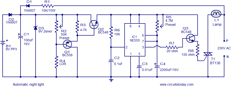
A simple and inexpensive automatic night light circuit designed using the timer IC NE555, which extinguishes after a preset time. This time can also be adjusted. The automatic night light circuit utilizes the NE555 timer IC configured in monostable mode....

This circuit effectively simulates various light sources such as a house fire, campfire, or welding light without the use of a microcontroller, although it requires a considerable number of components, including some uncommon ones. It is based on three...