
clock generator circuit
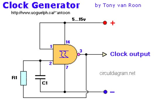
The clock generator circuit utilizes NAND gate logic to create a stable 1Hz output, ideal for applications requiring precise timing. The choice between the 7400 and 4011 ICs allows flexibility based on availability and performance requirements. The 7400, being a TTL device, offers faster switching times, making it suitable for high-speed applications, while the 4011 provides a cost-effective solution with adequate performance for most clock generation tasks.
The NE555 timer is a versatile component widely used in timing applications. Configured as an astable multivibrator, it continuously oscillates between high and low states, producing a square wave output. The frequency of oscillation can be finely tuned with the use of a potentiometer, allowing for customization of the clock signal to meet specific requirements. This feature is particularly beneficial in digital clock designs, where accurate timing is crucial.
The sound effect generator circuit utilizing the UM3561 chip is capable of producing a variety of audio outputs, making it suitable for applications such as doorbells or novelty sound effects. The integration of a transistor driver (2N3706) allows for the amplification of the audio signal, ensuring that the sound is audible in various environments.
The ticking bomb sound generator circuit provides an interesting application of timing circuits, utilizing a simple capacitor charge and discharge mechanism to create a recognizable ticking sound. This circuit can be used in toys or prank devices, adding an element of fun.
Lastly, the Western music generator circuit based on the HT82207 IC demonstrates the capability of integrated circuits to deliver complex functionalities in a compact form factor. This circuit can be used in various entertainment devices, showcasing the versatility of modern electronic design. Overall, these circuits illustrate the practical applications of timing and sound generation in everyday electronics.The following diagram is the Clock Generator circuit diagram which build based on NAND Gate logic IC. You may use IC 7400 or 4011 for this circuit. The 7400 is a TTL type, while 4011 is CMOS type. IC 4011 is cheaper than 7400 but the 7400 is faster than 4011. Circuit Notes: Excellent clock. This is the 1Hz clock generator circuit with Chip On Boa rd (COB). Commonly, the circuits to produce 1Hz clock for digital clock and counter circuits applications implement ICs in conjunction with a crystal and trimmer capacitors, etc. Even so, equivalent or improved accuracy could be obtained working with a chip-on-board (COB) device found inside a.
This is the door bell circuit with flashing LEDs to make the circuit more attractive. IC1 (NE555) is applied right here as being a clock generator. It is actually set up as an astable multivibrator whose frequency could be altered using the support of potensiometer VR1. The clock pulses received from IC1 are fed to. This is a really simple sound effect generator based single sound generator chip UM3561. The UM3561 will generate four kinds of sound effects. The basic operation is that the UM3561 will generate the sound signal, then the signal delivered to 2N3706 (as speaker driver) to be amplified so you can hear the sound from a.
Here the low cost and easy build circuit of ticking bomb sound generator. This circuit generates a sound matching to a loud clicking clock. The frequency of the tick is altered through the 220k potensiometer part. The circuit gets going by charging the 2. 2uF and when 0. 65v is on the base of the NPN transistor, . This is the schematic diagram of Western music generator circuit based on single IC HT82207. This circuit is able to take you towards the world of the Wild West. The western music already programmed in the chip. It utilizes the integrated 18-pin HT82207 (IC1) of Holtek, which literally takes care of almost everything. You`ve to. 🔗 External reference
Related Circuits
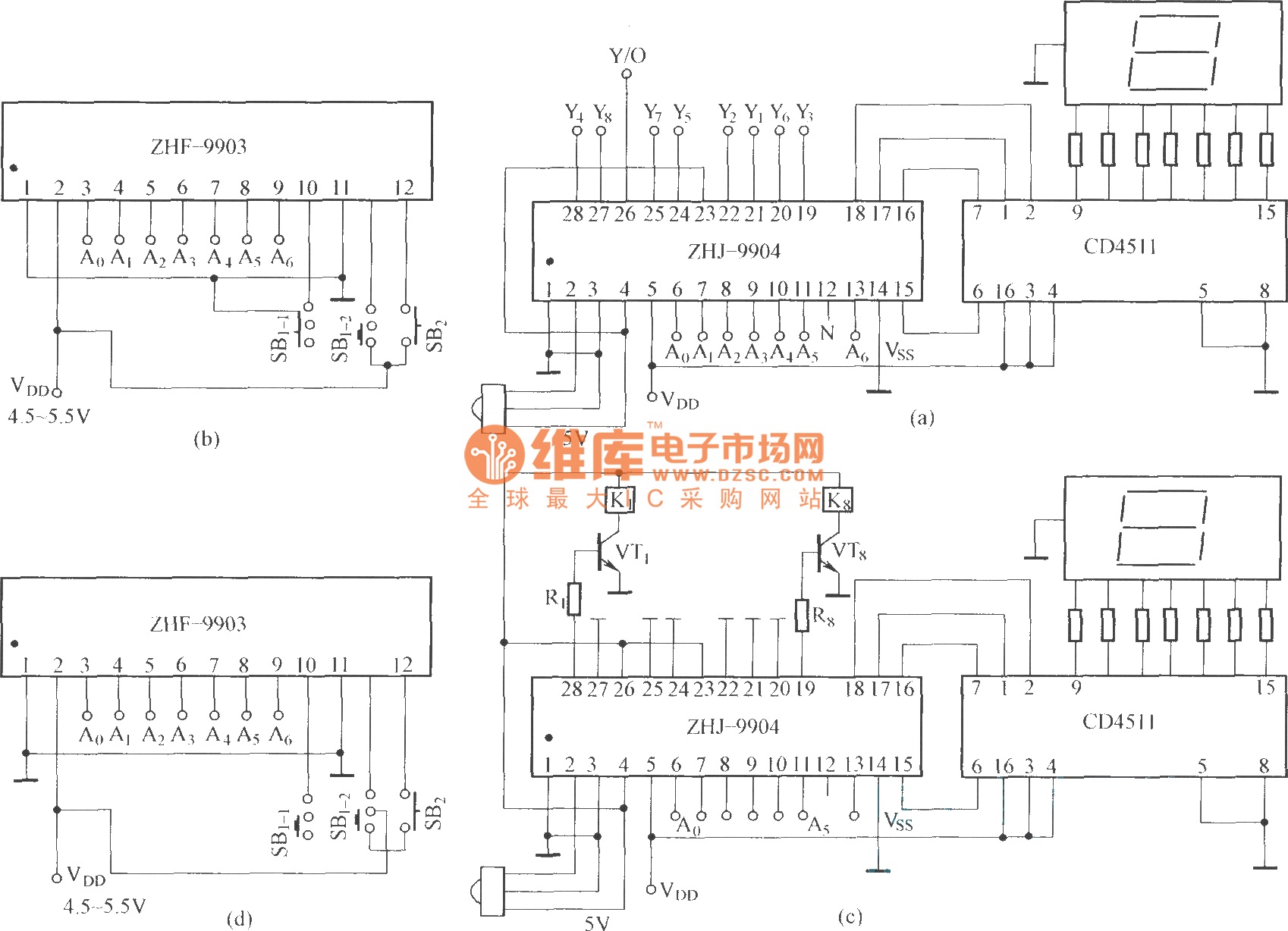
This is an eight-way signal remote control selection circuit composed of ZHJ-9904. It includes a remote control transmitter circuit, an eight-way switch control circuit, and a remote control transmitter. The eight-way signal remote control selection circuit utilizing the ZHJ-9904 is...
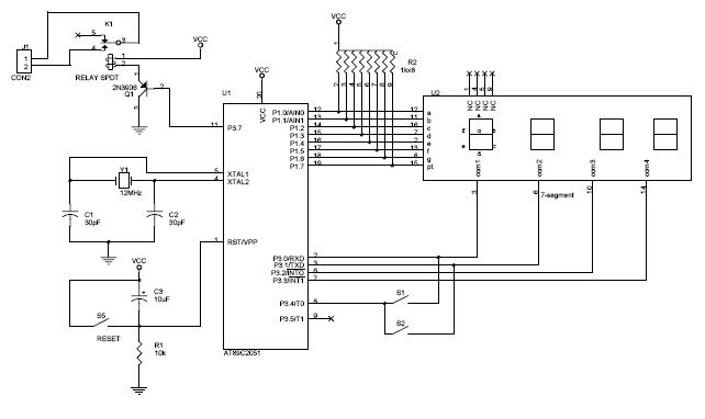
The circuit diagram above illustrates the Clock Controller V1.1. Pins P3.0 to P3.3 are connected to the base of a 4-PNP transistor, specifically the 2N2907, which is used to sink current. The Clock Controller V1.1 circuit is designed to manage...
This digital DIY tachometer for bicycles utilizes two reed switches to gather speed information. The reed switches are positioned near the wheel rim, where permanent magnets, attached to the wheel spokes, pass by and activate the switches. The speed...
Just point this small device at the TV and the remote gets jammed. The circuit is self-explanatory. 555 is wired as an astable multivibrator for a frequency of nearly 38 kHz. This is the frequency at which most of...
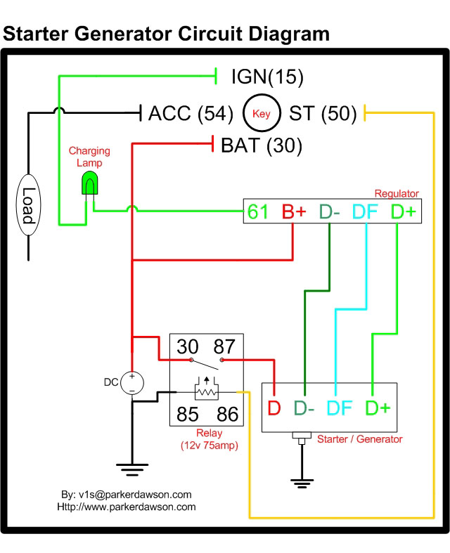
Circuit diagrams for both a Bosch and a Delco-Remy Starter-Generator are available, noting that the circuits differ. Due to a computer crash, the original diagrams and the associated email address were lost. However, in May 2004, both the email...
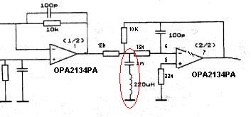
Can someone explain why there is an LC filter in the op-amp circuit? Additionally, are there any modifications that can be made to enhance the sound quality? The presence of an LC filter in an operational amplifier (op-amp) circuit serves...