
Simple Siren Circuit
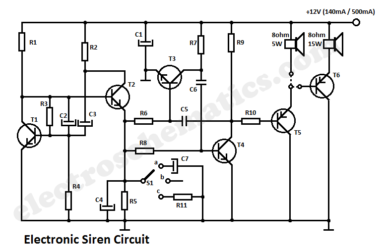
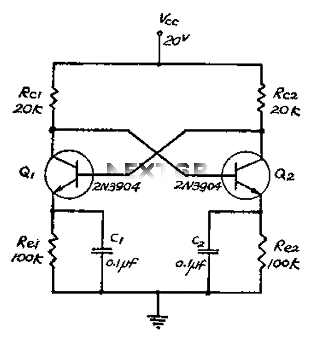
The described circuit employs a free-running multivibrator configuration utilizing both PNP and NPN transistors, which facilitates the generation of oscillating signals. The multivibrator's operation hinges on the charging and discharging cycles of capacitor C1, which is influenced by resistor R1. When switch S1 is engaged, the charging process of C1 introduces a time delay that is governed by the RC time constant, defined by the resistance of R1 and the capacitance of C1. As the voltage across C1 builds up to 4 volts, it effectively alters the timing characteristics at the junction of R2 and C2.
The RC circuit comprising R2 and C2 plays a critical role in modulating the frequency of the output signal. As the voltage at the junction decreases due to the charging of C1, the time constant at this point decreases, resulting in a higher frequency output from the multivibrator. This creates a rising tone characteristic of a siren. Conversely, once S1 is released, C1 begins to discharge, which increases the time constant at the R2/C2 junction, leading to a reduction in frequency and thus a falling tone.
The output waveform is a sawtooth shape, characterized by its linear rise and sudden drop, which effectively mimics the sound of a siren. This waveform can be further processed or amplified to drive speakers or other audio devices, enhancing the siren effect. The careful selection of resistor and capacitor values allows for tuning the frequency range and the duration of the rising and falling tones, making this circuit versatile for various applications where siren-like sounds are required.This circuit generates a tone that sounds very similar to a siren. The generator part of the circuit is made of the combination of PNP and NPN transistors. Toghether, the two transistors build up a free runing multivibrator. If the C2 capacitor was connected to the positive line of the power supply, it would have worked as a constant frequency osc illator. However, we dont want a constant frequency oscillator. We want a siren. So to generate an up and down going signal tone, the resistor R2 is fed from an RC circuit. When the switch S1 is pressed, the capacitor C1 charges via R1 slowly until it reaches the maximum voltage level of 4 volts. This increasing voltage results to a decreasing time constant at the R2/C2 junction. This furthermore results to an increasing frequency of the multivibrator. After the switch S1 is released, the capacitor C1 discharges slowly resulting to a decreasing frequency cycle.
Through the combination of the two time constants a sawtooth waveform is generated. 🔗 External reference
Related Circuits
The TDA7294 amplifier module is a monolithic integrated circuit designed for use as a Class AB audio amplifier in high-fidelity applications. It features a wide voltage range and output current capability, allowing it to deliver high power to both...
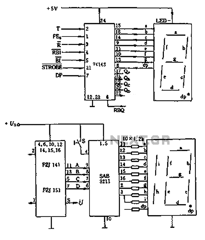
The decimal seven-segment storage decoding drive unit 74HC143 provides a constant output for all segments, each at a voltage of 5V and a current ranging from approximately 15mA to 22mA. The BCD data for the seven-segment decoder can be...
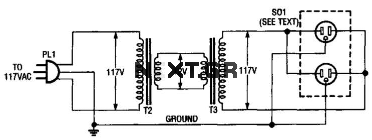
An isolation transformer for low-power applications (under 50 W) can be constructed using two 12-V filament or power transformers. This setup includes a standard duplex AC receptacle. It is important to utilize heavy-wire connections between the 12-V windings, as...

The ordinary triode 3DA87C is utilized to create a long-range FM transmitter circuit, which functions as a standard three-point oscillator circuit. This remote transmitter circuit is capable of large current emissions, achieving a range of up to 1 kilometer...
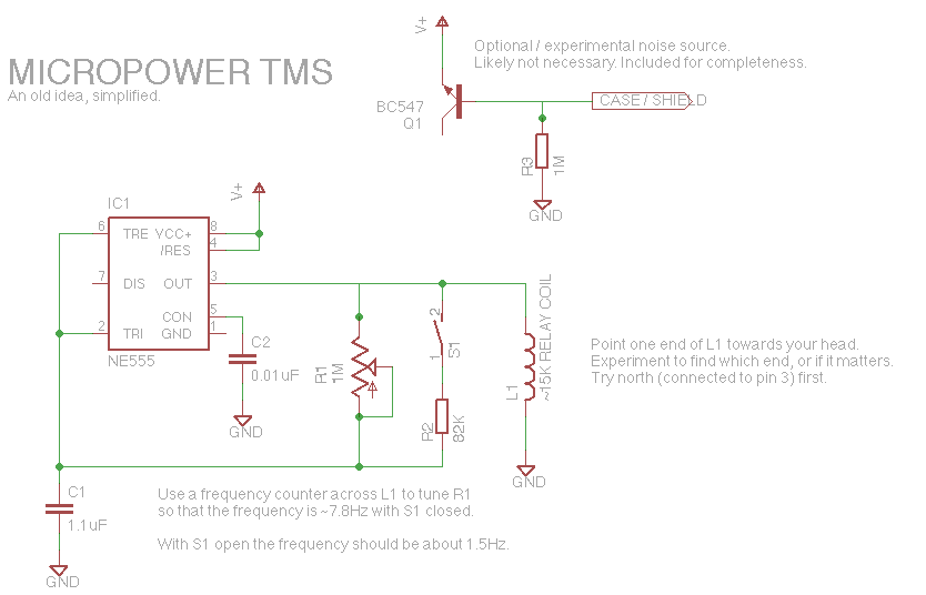
Let's face it, not every day is the greatest. Sometimes, one may not feel like doing much of anything. Wouldn't it be nice if there was a way to change brain waves at the push of a button? Transcranial...
The collector and base-emitter bias of the transistor are directly coupled to each other. Each transmitter circuit controls the capacity conversion function. The emitter generates a triangular wave. The two transistors are not continuously in an active state. Instead,...
Warning: include(partials/cookie-banner.php): Failed to open stream: Permission denied in /var/www/html/nextgr/view-circuit.php on line 713
Warning: include(): Failed opening 'partials/cookie-banner.php' for inclusion (include_path='.:/usr/share/php') in /var/www/html/nextgr/view-circuit.php on line 713