
Wireless keyboard circuit
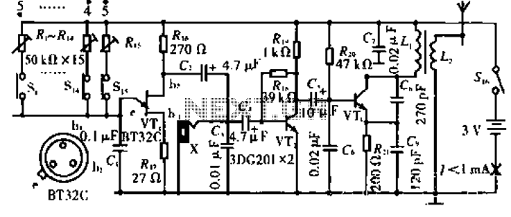
The described circuit utilizes a common-base configuration for VT3, which is effective in providing high-frequency oscillations. The oscillation frequency is critically determined by the values of capacitors C8 and C9 in conjunction with inductor L1, which forms a resonant tank circuit. This tank circuit is essential for establishing the desired frequency of oscillation, allowing for precise tuning of the circuit's output.
VT2, functioning as a voltage amplification stage, plays a crucial role in enhancing the amplitude of the audio signal before it is fed back into the circuit. This feedback mechanism is vital for maintaining the oscillation and ensuring the stability of the output signal. The modulation of the high-frequency signal by the audio input is achieved through the interaction with L2, which serves as a coupling inductor, facilitating the transfer of energy and information between the high-frequency oscillator and the audio signal path.
The overall design of this circuit is particularly suited for applications requiring amplitude modulation of audio signals, such as in communication systems or audio processing equipment. The careful selection of component values and the configuration of the circuit elements are paramount for achieving optimal performance, including desired frequency response and signal integrity.Circuit works:, VT3 and peripheral components configured as a common-base capacitance feedback oscillation circuit, the oscillation frequency is determined by C8, C9, L1. VT2 voltage amplification stage, and put back the audio signal with a large amplitude to the high frequency signal VT3 is amplitude modulated with high frequency signal emitted by the L2.
Related Circuits
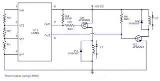
The values of the LM56 thermostat project circuit diagram for resistors R1, R2, and R3 at the travel points VT1 and VT2 can be determined using the following equations. This electronic circuit thermostat with the IC LM56 serves as...
This circuit is designed to demonstrate high-frequency high voltage, capable of producing voltages up to approximately 30 kV, depending on the transformer used. It is economical and straightforward to construct, primarily utilizing a standard TV flyback transformer. The circuit...
Schematic and description of a simple automatic NiMH battery charger circuit using IC 7805 with multiple selectable current options for charging. The described circuit is a straightforward automatic charger designed for Nickel-Metal Hydride (NiMH) batteries. It utilizes the IC 7805...
This is a follow-up to an earlier post regarding a specific circuit schematic. The circuit is designed to operate at a supply voltage of 5V, and testing has confirmed that the original device functions correctly at this voltage. A...
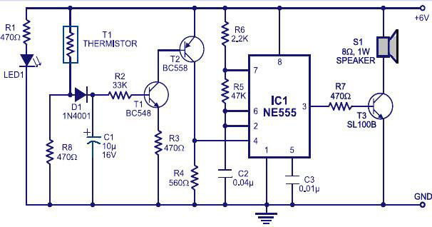
Various fire alarm circuits are discussed, featuring a new design that utilizes a thermistor and a timer. This circuit is straightforward and can be easily implemented. The thermistor exhibits low resistance at high temperatures and high resistance at low...
Introduction The MIC2290 is an internally compensated standard step-up switching regulator that features an integrated power switch and Schottky diode. The inclusion of these components makes the MIC2290 an optimal solution for 48V Avalanche Photo Diode (APD) applications. In...