
Guitar tube amplifier Peavey schematic
The provided description indicates modifications to an existing electronic circuit. The changes involve the replacement of certain parameters and components as denoted by color coding. Specifically, values that were previously marked in blue have been substituted with new values represented in red. This suggests a recalibration or adjustment of the circuit's operational characteristics, potentially enhancing its performance or aligning it with new specifications.
Additionally, the removal of blue components signifies that certain elements of the circuit have been deemed unnecessary or obsolete, thereby streamlining the design. The introduction of red components indicates the addition of new elements that likely serve a specific function, possibly improving the circuit's efficiency or expanding its capabilities.
The mention of moving the relay mute contacts to the other side of capacitor C21 suggests a potential redesign of the circuit layout. This alteration could be aimed at optimizing the physical arrangement of components to minimize interference, improve accessibility, or enhance signal integrity. The relay mute contacts are crucial for controlling audio signals, and repositioning them could lead to better performance in applications such as audio processing or signal routing.
Overall, these modifications reflect a systematic approach to circuit design, emphasizing the importance of adaptability and precision in electronic engineering. The adjustments made to values and components, along with the proposed layout change, are indicative of a thorough evaluation of the circuit's functionality and an intent to refine its overall design.Blue VALUES replaced by values in RED. Blue COMPONENTS removed from circuit. Red components added to circuit. Optional: move relay mute contacts to other side of C21. 🔗 External reference
Related Circuits
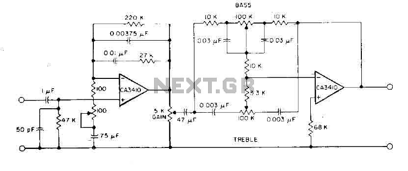
This circuit incorporates RIAA equalization, tone controls, and sufficient gain to drive most commercial power amplifiers using the CA3410 op-amp BiMOS. The total harmonic distortion is minimized to less than 0.035% for an output of 6 V within the...
The IC1A operational amplifier is configured as an inverting amplifier, with its gain determined by a three-way switch that connects different resistor values in parallel to R4. Following this input stage is an active three-band tone control circuit, designed...
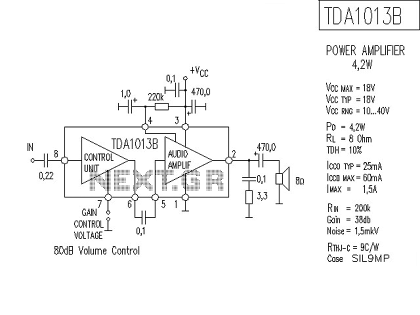
The following is a circuit for a 4-watt audio amplifier. The amplifier utilizes an integrated audio amplifier chip, TDA1013B, which is capable of delivering an audio power output of up to 4W at an 8-ohm load. Its wide supply...
The Up Alarm is designed to provide an audible alert when sunlight is detected or when a light source is activated in a dark environment. It can also be utilized to sense various light sources such as beams or...
The test beeper generates a sinusoidal signal with a frequency of 1,000 Hz, which is a standard test frequency for audio amplifiers. It utilizes a Wien-Bridge oscillator configuration, also referred to as a Wien-Robinson oscillator. The frequency-determining network comprises...
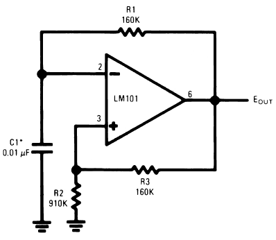
The timing capacitor (C1) generates multiple time constants, facilitating substantial voltage fluctuations at the input, attributable to the LM101's extensive input voltage range. It is advisable to decrease the value of resistor R2 and to increase the capacitance of...
Warning: include(partials/cookie-banner.php): Failed to open stream: Permission denied in /var/www/html/nextgr/view-circuit.php on line 713
Warning: include(): Failed opening 'partials/cookie-banner.php' for inclusion (include_path='.:/usr/share/php') in /var/www/html/nextgr/view-circuit.php on line 713