
electronic dice circuit
The electronic dice circuit utilizes a 555 timer in astable mode, which produces a continuous square wave output. This output serves as the clock signal for the BCD counter, typically a 74HC390 or similar IC, which counts from 0 to 9 in binary-coded decimal format. The counter is connected to a series of LEDs through a resistor network to limit the current and prevent damage to the LEDs. The arrangement of the LEDs simulates the faces of a die, with outputs corresponding to the values 1 through 6.
To ensure the output does not exceed the maximum value of 6, the two AND gates are strategically placed in the circuit. They monitor the BCD output, and when the count reaches seven, they send a reset signal to the BCD counter, forcing it back to one. This mechanism prevents the circuit from displaying an invalid die face.
The overall design can be enhanced by incorporating additional components, such as a debouncing circuit for the pushbutton switch, which would help to eliminate any unwanted multiple counts caused by mechanical bounce. Furthermore, a capacitor can be added to the 555 timer circuit to adjust the timing interval, allowing for customization of the dice rolling speed.
In summary, this electronic dice project combines fundamental electronic components, such as timers, counters, and logic gates, to create an engaging and interactive device that can enhance traditional gaming experiences. The design's simplicity and reliance on basic electronic principles make it an ideal project for beginners in the field of electronics.An electronic dice is a classic first project for those getting interested in electronics. A timer, counter and a few LEDs makes a circuit that can also add a new twist to some old boring board games. When the switch is pressed, a 555 timer in astable mode pulses a BCD counter which lights up a series of LEDs wired to mimic a dice.
Two AND gates a re used to reset the count back to one whenever the BCD output is seven. Thus, the circuit is not truly random but the natural bounce present in a pushbutton and the normal human ability to operate much slower then the oscillator make the output of the circuit seem random. 🔗 External reference
Related Circuits

One of the key challenges in the design of 4- to 20-mA current transmitters is the voltage-to-current conversion stage. Conventional transmitters use multiple op amps and transistors to perform the conversion function. These approaches have been around for a...
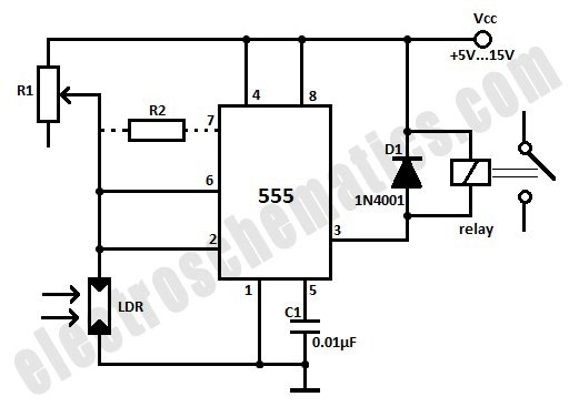
This light-activated relay circuit utilizes the 555 timer integrated circuit (IC) and a light-dependent resistor (LDR) to create a light-sensitive relay suitable for applications such as intruder alarm systems or automatic lamp control at sunset and sunrise. The potentiometer...

This project outlines a simple remote control system utilizing RF communication without a microcontroller. The remote is designed to operate various home appliances such as televisions, fans, and lights, providing convenience by allowing users to control devices from a...

In the absence of light, photocells PC1 and PC2 exhibit high resistance, causing transistors Q1 and Q2 to remain off, which prevents the relay contacts K1 and K2 from closing. The battery B3 is connected through a potentiometer Rs,...
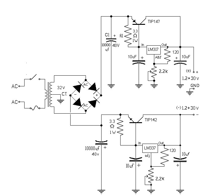
The 10A variable power supply circuit is symmetrical and can provide a symmetrical output voltage ranging from ±1.2 volts to ±30 volts DC, with a maximum current of 10A. This circuit utilizes symmetrical variable voltage regulators LM317 and LM337,...
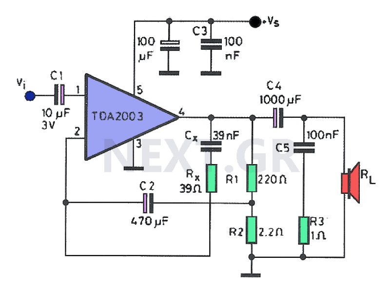
Often, a small amplifier is required to accommodate the needs of compact spaces. This amplifier can be configured as either mono or stereo, and its circuitry is capable of efficiently driving two small speakers. Constructing the amplifier necessitates only...