
Electronic Drum Synthesizer
The circuit utilizes twin-T oscillator configurations, which are known for their ability to generate sine wave signals. Each oscillator consists of resistors and capacitors arranged in a specific manner to create a band-pass filter characteristic. In this design, the oscillators are intentionally set below the oscillation condition, meaning they require an external stimulus to start oscillating.
The Touch Pad serves as a user interface element that provides the necessary feedback to the circuit. When pressure is applied to the Touch Pad, it introduces a perturbation that allows the oscillators to reach their oscillation point. The capacitive nature of the Touch Pad may also contribute to the circuit's sensitivity, enabling it to detect even slight touches.
The circuit's design may include additional components such as operational amplifiers to amplify the output signal, ensuring that the generated waveform is strong enough for further processing or output. The output can be connected to various devices, such as speakers or additional circuitry, depending on the application.
In summary, this circuit exemplifies a simple yet effective method of generating oscillations using twin-T oscillators, with the Touch Pad providing a tactile means to initiate the oscillation process. The design is versatile and can be adapted for various applications in audio synthesis, signal processing, or educational demonstrations of oscillation principles.The circuit below consists of two `twin-T` oscillators set to a point below oscillation. To set the circuit into oscillation, we can touch the Touch Pad. Here . 🔗 External reference
Related Circuits
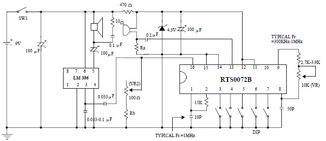
This voice changer circuit diagram is an electronic project developed using the RTS0072B single-chip CMOS LSI, specifically designed for voice-changing applications. It can transpose or distort one voice into another by encoding the input audio signals at normal speed...
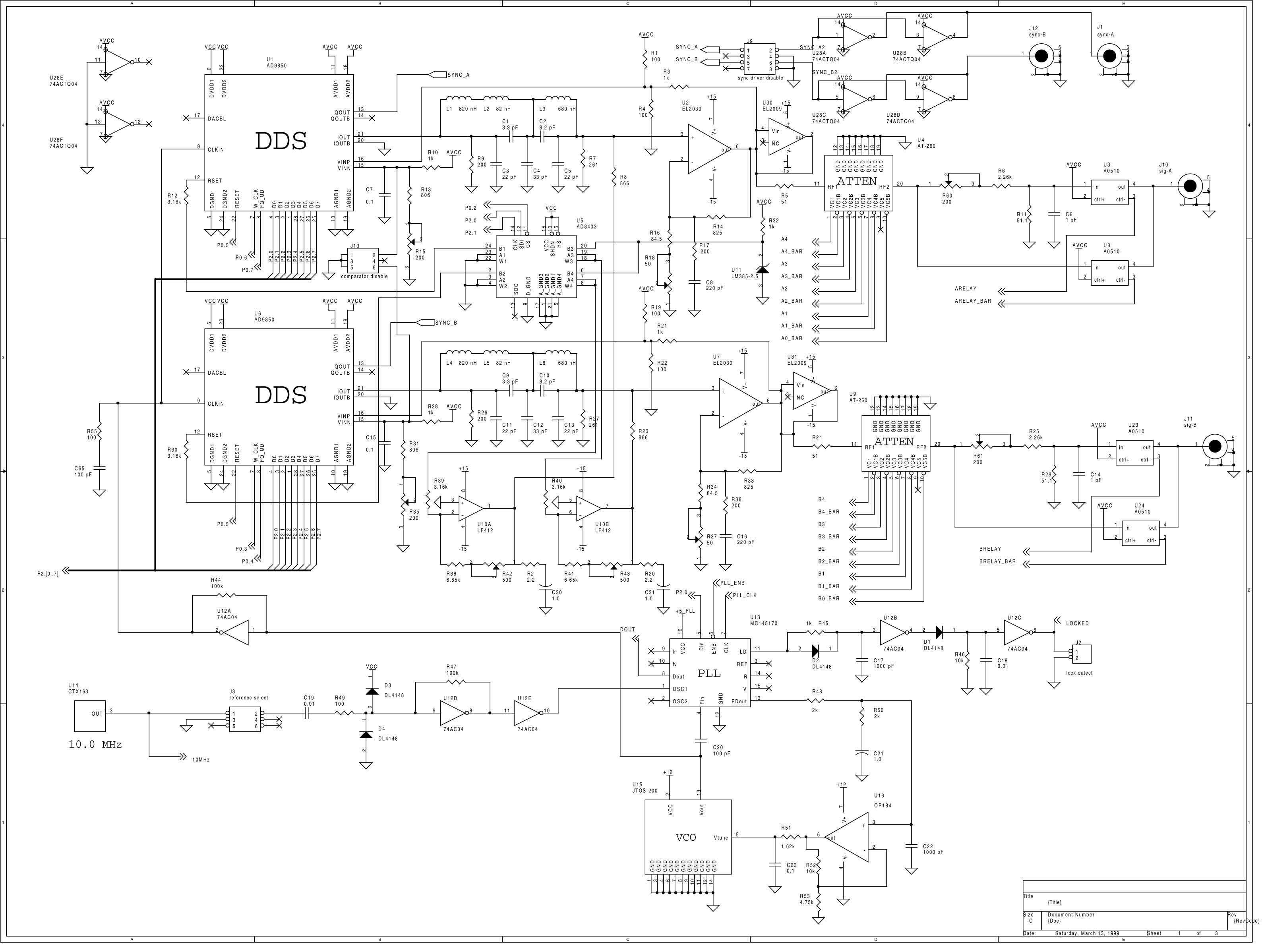
This instrument is a one or two channel frequency synthesizer. DC to 35 MHz frequency with 0.1 Hz resolution. +16 to -48 dBm signal level with 0.1 dB resolution. adjustable phase between the 2 channels with 11.25 degree resolution....
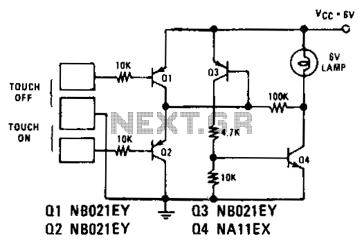
Transistors Q1 and Q2 control latches Q3 and Q4 to switch on the lamp. A high resistance from touching the electrode biases Q1 or Q2 on, setting or resetting the latch. In this circuit, transistors Q1 and Q2 function as...
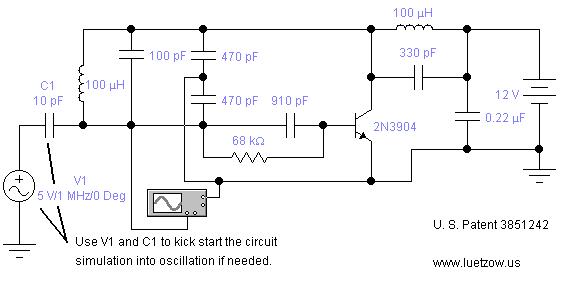
The oscillator circuits presented on this page are derived from expired or non-maintained U.S. Patents. All circuits are formatted for "Electronic Workbench 5.12" or "Multisim 7" circuit simulation software. A note regarding SPICE simulation of electronic oscillator circuits: all...
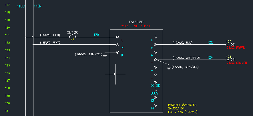
The power supply unit (PSU) in question does not appear to be exceptionally large. Eagle software should be capable of managing these dimensions. The focus was more on finding an alternative that may already include the necessary components and...
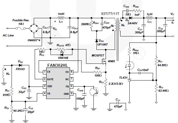
A simple 5-volt switching power supply electronic circuit project can be designed using the FAN302HL, a highly integrated PWM controller integrated circuit. This IC provides several features that enhance the performance of general flyback converters. The constant-current control of...
Warning: include(partials/cookie-banner.php): Failed to open stream: Permission denied in /var/www/html/nextgr/view-circuit.php on line 713
Warning: include(): Failed opening 'partials/cookie-banner.php' for inclusion (include_path='.:/usr/share/php') in /var/www/html/nextgr/view-circuit.php on line 713